A systematic factory design process serves as a technical guideline that ensures industrial projects operate efficiently and safely from the initial stages. In practice, skipping or inadequately conducting site surveys and technical documentation reviews often leads to serious risks, including foundation and floor settlement, conflicts between MEP infrastructure systems, unexpected construction costs, and delays in fire protection approval procedures.
Understanding each standardized stage of the process, combined with comprehensive consulting solutions from BIC as a general construction contractor, enables investors to maintain full control over factory design and construction. This approach helps optimize factory functionality, improve space utilization efficiency, and ensure that the entire project commences commercial production operations according to the planned schedule.
Data collection and site surveys form the initial foundation of the factory design process, providing architects and structural engineers with all necessary technical parameters based on actual site conditions. Accurately collecting existing condition data helps establish safe, feasible, and cost-effective construction design solutions for foundations and supporting infrastructure.
Hydrogeological investigations begin with establishing an exploratory drilling grid on-site to collect soil and rock samples from different depths. Laboratory analysis results provide accurate information about the bearing capacity of natural soil, compaction characteristics, and seasonal groundwater fluctuations. These findings are essential for engineers to select between shallow foundations and reinforced concrete pile foundations, thereby preventing the risk of structural settlement. At the same time, topographical surveying involves preparing terrain maps based on the national VN-2000 coordinate reference system to accurately determine site boundaries and natural ground elevations. Survey data enable the general construction contractor to calculate the balance between excavation and filling quantities required for site leveling, helping investors control site preparation costs from the beginning.

The consulting team conducts on-site inspections of external infrastructure connection points serving the industrial park. The parameters to be determined include the available capacity of medium-voltage or low-voltage electrical supply networks, water supply pipeline pressure, public stormwater drainage channel elevations, and the wastewater acceptance standards of centralized treatment facilities. In addition, reviewing architectural and planning parameters established by the industrial park management authority is mandatory. Requirements concerning maximum building density, floor area ratio, permitted building height, and building setbacks from road boundary lines establish a fixed legal framework. Strict compliance with these regulations ensures that factory design documentation meets the necessary requirements when applying for construction permits.
Alongside on-site surveys, the general construction contractor obtains production process diagrams and machinery equipment lists from the investor. Information concerning overall equipment dimensions, self-weight, static loads, and dynamic loads generated during machinery operation is recorded in detail to design specialized equipment foundations or heavy-duty industrial floor systems. In addition, specific working environment requirements, including stable temperature and humidity ranges, air cleanliness standards, and warehouse material handling needs, are comprehensively collected. All this information is integrated into the overall construction design process to ensure that the completed factory fully meets its intended production and operating conditions.
After collecting sufficient site data, the next step in the process is developing the basic design proposal. This stage provides investors with an overall understanding of the project's architectural form, functional layout arrangements, and technical infrastructure systems.
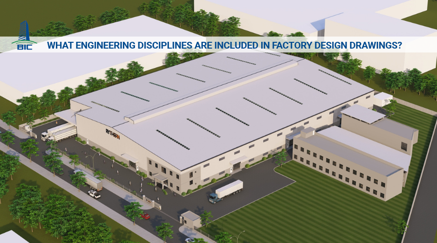
Architects prepare a 1:500 master site plan that clearly identifies the locations of the main production workshop, raw material warehouse, finished goods warehouse, administrative office building, employee cafeteria, and electrical substation. Functional zoning must strictly follow the principle of one-way production flow, ensuring that materials move continuously without overlapping or conflicting routes. Internal traffic systems are planned to completely separate pedestrian routes for workers, forklift circulation routes for internal material transportation, and container truck access routes serving warehouse loading and unloading operations.

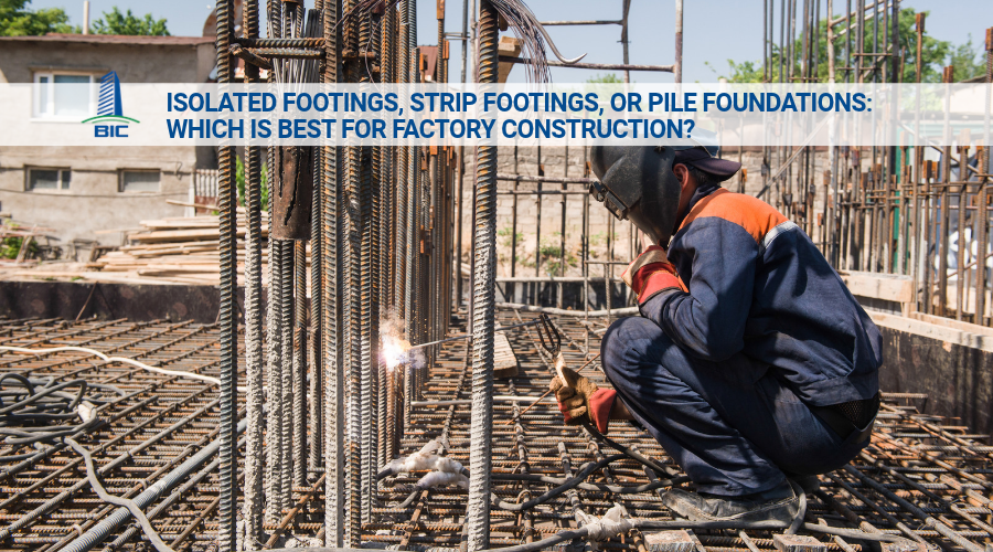
Based on geotechnical analysis results, structural engineers recommend the most suitable foundation solution. For soil with adequate bearing capacity, shallow reinforced concrete foundations are prioritized to reduce construction costs. Where weak soil conditions exist, driven concrete pile foundations or bored pile solutions are incorporated into the construction design proposal. The factory superstructure typically uses large-span pre-engineered steel frames to maximize usable production space. The building envelope combines high-quality insulated metal roofing systems with thermal insulation panels, ensuring structural durability, industrial aesthetics, and reduced electricity consumption for cooling systems.
Preliminary MEP infrastructure solutions are developed through electrical power distribution diagrams, factory lighting networks, transformer station locations, and designated spaces for backup generators. HVAC ventilation and cooling solutions are outlined according to the specific requirements of each manufacturing industry. In addition, preliminary solutions for internal water supply and drainage networks, automatic fire protection systems, and industrial wastewater treatment facilities are incorporated into the documentation package. Coordinated calculations during the basic design stage enable investors to accurately evaluate project feasibility and estimate the overall investment budget.
The technical design stage involves developing preliminary solutions into detailed engineering documentation suitable for submission to regulatory authorities responsible for fire protection safety, environmental compliance, and construction permitting.
During this stage, engineers conduct detailed calculations of reinforced concrete foundation load-bearing capacity, the structural strength of pre-engineered steel columns and rafters, operational overhead crane loads, and the compressive load-bearing capacity of industrial factory floors. Structural stress data are analyzed using specialized engineering software to ensure the highest level of safety. MEP infrastructure systems are further developed through detailed electrical power distribution diagrams, transformer capacity calculations, cable ladder and cable tray dimensions, water supply and drainage pipeline layouts, and flow requirements for supporting compressed air systems.
Fire protection design documentation is prepared in accordance with applicable safety standards, including layout drawings for automatic sprinkler heads, automatic fire alarm networks, fire pump station locations, and fire-resistant coating systems protecting structural steel frames. Specialists from BIC, acting as the general construction contractor, directly represent investors in submitting documentation, providing technical explanations, and presenting design solutions to the competent fire prevention and fighting authorities. Standardizing the documentation package from the beginning helps shorten fire protection approval procedures and ensures that project schedules are not disrupted by administrative obstacles.
Alongside fire protection approval procedures, the technical design documentation is submitted to an independent verification consultant with appropriate professional qualifications to assess structural load-bearing safety and compliance with applicable construction regulations. After receiving the verification results and completing the necessary technical adjustments, the investor or BIC, as the general construction contractor, compiles the complete legal documentation package, Environmental Impact Assessment (EIA) report, and technical design documents for submission to the competent regulatory authority to obtain a construction permit.
Construction drawing documentation represents the most comprehensive technical deliverable, specifying detailed parameters required for component fabrication and on-site installation.
The construction drawing package precisely specifies the geometric dimensions of individual steel columns and beams, details of load-bearing bolted connections, foundation reinforcement arrangements, and locations of recessed floor pits. For MEP infrastructure, the drawings accurately indicate cable ladder elevations, fire protection pipeline routes, water supply and drainage pipelines, and final equipment installation locations. The comprehensive level of detail in these drawings enables supervising engineers and construction workers to execute work accurately on-site, eliminating technical errors caused by misinterpretation of design documentation.

Based on the finalized construction drawing package, the cost estimation team prepares detailed quantity takeoffs for each project component. The Bill of Quantities (BOQ) provides a transparent breakdown of material categories, technical specifications, actual construction quantities, and estimated unit prices. This information helps investors maintain strict control over capital expenditure (CAPEX) and prevent additional costs beyond the agreed contract. At the same time, a critical-path schedule is developed to closely coordinate structural steel fabrication at manufacturing facilities with on-site foundation construction activities.
BIC applies three-dimensional Building Information Modeling (BIM) technology to review the entire construction documentation package. By integrating architectural, structural, MEP, and fire protection disciplines into a unified 3D model, the software automatically identifies technical clashes, such as drainage pipelines intersecting steel beams or electrical cable ladders conflicting with fire protection pipelines. Resolving these conflicts completely within the digital environment ensures that construction drawings issued to the site achieve the highest level of completeness, supporting efficient construction execution and adherence to project schedules.
Following a systematic factory design process, from geotechnical investigations and basic design development to fire protection approval and final construction drawings, is a decisive factor in the success of every industrial project. Standardizing each implementation stage not only helps investors prevent legal risks and structural settlement but also maximizes control over investment costs and construction schedules. Partnering with BIC as a general construction contractor provides comprehensive consulting solutions under the Design and Build model. With advanced 3D BIM technology capabilities and extensive practical project experience, BIC is committed to delivering integrated construction design solutions that optimize functionality, ensure fire protection safety, and enable factories to commence commercial production operations according to the planned schedule.