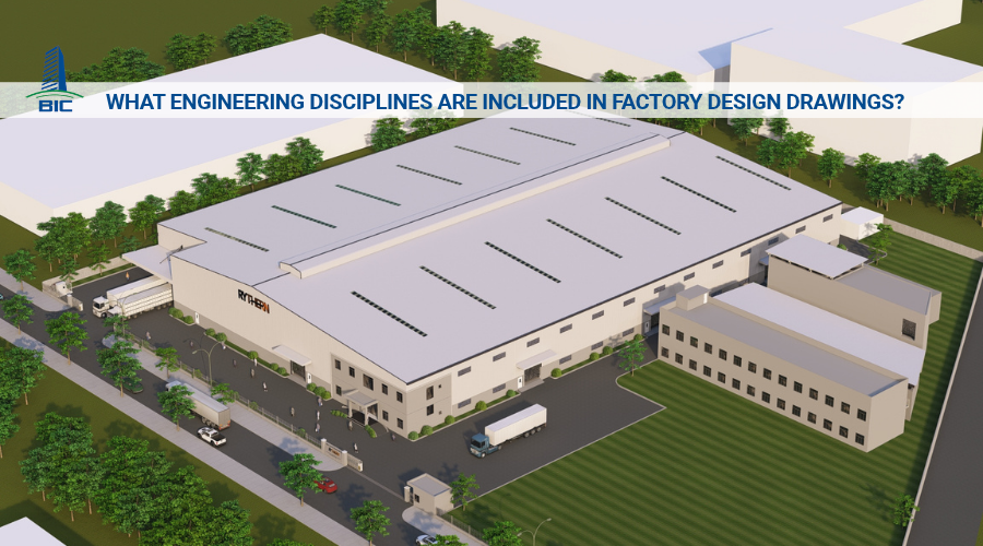
In industrial construction, architectural drawings serve primarily as the protective envelope, while the production process layout is the core element determining the operational efficiency of the entire factory. Factory design that is disconnected from machinery operations and material flow can lead to significant problems once the facility begins operating. Common consequences, including transportation bottlenecks, wasted warehouse space, excessive material handling labor costs, and the need to demolish concrete floors to install additional machinery foundations, all stem from designs that fail to adequately reflect actual production requirements.
To develop a factory that operates efficiently, investors must place production process layouts at the center of the project planning stage. With the technical expertise and practical experience of BIC as a general construction contractor, construction design drawings accurately developed around each manufacturing stage not only help minimize monthly operating expenses but also facilitate future capacity expansion. This article examines the fundamental principles, effective production line layout models, and coordination solutions between investors and design and construction contractors to deliver industrial facilities that meet quality standards.
A properly designed industrial factory is not merely an architectural structure but a large-scale production system containing numerous interconnected machines. The relationship between architectural drawings and production technology drawings is an integrated one: architectural and structural systems must be adaptable enough to fully support the manufacturing process. Beginning factory design with the production process is essential to ensuring that the facility operates smoothly from its first day of operation.
Modern industrial construction approaches reject the practice of constructing an empty warehouse and subsequently attempting to fit machinery inside it. All building dimensions and geometric parameters must be determined by the dimensions and operational characteristics of the production line:
- Clear height: Calculated based on the maximum equipment height, together with the required safety clearance for overhead crane operations or the height of pallet racking systems.
- Structural spans and column grids: Selecting column spacing of 6 m, 9 m, or 12 m depends directly on production equipment dimensions and forklift turning radii. Appropriate column spacing helps optimize usable floor area and eliminates dead spaces where machinery cannot be installed or where vehicles may collide with structural components.
- Roof structural load-bearing capacity: Additional load allowances must be calculated when production lines require heavy cable trays, centralized ventilation ducts, or roof-supported overhead cranes.

Scientifically arranging production lines in construction design drawings is a direct method of reducing long-term operating expenses for businesses:
- Shortening production cycle time: Arranging consecutive production stages along a continuous material flow minimizes the distances traveled by semi-finished products. Reduced idle time between processes increases production output per working shift.
- Reducing internal logistics costs: Optimized forklift transportation routes reduce energy consumption, including electricity and fuel, lower vehicle maintenance frequency, and eliminate unnecessary material handling labor.
- Optimizing lighting and cooling costs: Clearly defined production zones enable engineers to concentrate lighting and ventilation systems in areas where employees work, preventing energy waste in unoccupied spaces or low-traffic storage areas.
Industrial machinery installation requires a high level of precision in technical infrastructure. Determining production line locations in advance helps ensure accurate factory construction:
- Positioning independent machinery foundations: Heavy machinery or equipment generating substantial vibrations, such as stamping presses, plastic injection molding machines, and air compressors, requires separate reinforced concrete foundation drawings. These foundations must be isolated from surrounding factory floors using expansion joints. This prevents floor cracking and limits the transmission of vibrations that could affect the precision of nearby CNC machining equipment.
- Accurate MEP connections: The locations of power distribution cabinets, underground electrical cables, water supply and drainage pipes, compressed air pipelines, and industrial wastewater collection points are precisely positioned and installed underground or within designated routes to serve each machine. This eliminates disorganized electrical wiring across factory floors, improves workplace safety, and creates a professional working environment.
- Coordination by the general construction contractor: When the general contractor fully understands the technical specifications of each machine, MEP infrastructure and structural construction can be coordinated seamlessly, avoiding the need to demolish concrete floors or modify cable trays after completion.
Every manufacturing industry has specific characteristics regarding raw material dimensions, automation levels, the number of production stages, and the frequency of semi-finished product transfers. In factory design, selecting an inappropriate layout model not only increases monthly operating costs but also creates significant obstacles when businesses seek to upgrade technology or expand production capacity.
The following is an in-depth technical analysis of the four most common production layout models, helping investors and project management teams make informed decisions during the master site planning stage.
The straight-line layout arranges all machinery, equipment, and workstations along a continuous production line in the exact sequence of the manufacturing process. Raw materials enter at the beginning of the line, while packaged finished products exit at the opposite end, following a one-way flow principle.
- Operating mechanism: This layout operates based on highly repetitive processes and extensive task specialization. Each workstation performs a fixed operation, while semi-finished products move continuously through conveyor belts, roller systems, or Automated Guided Vehicles (AGVs).
- Internal logistics optimization: Eliminates intersecting traffic routes and backtracking movements. This helps shorten production cycle time, minimize Work-in-Process (WIP) inventory accumulated on factory floors, and prevent collisions between internal transportation vehicles.
- Impact on structural and MEP drawings: The factory typically requires a long, narrow configuration with a high length-to-width ratio. Electrical distribution cabinets and compressed air connection points are arranged along the longitudinal axis of the building.
- Limitations: Extremely limited flexibility. If one production stage experiences a technical failure, the entire production line may need to stop. In addition, changing product categories may require restructuring the entire production line.
- Suitable applications: High-volume manufacturing industries with limited product variety and highly standardized processes, including industrial garment factories, beverage bottling plants, electronic component manufacturing, motorcycle assembly, and steel sheet and purlin rolling facilities.

The U-shaped layout is an improved variation of the straight-line configuration, in which the entire production line is arranged in a U shape. The raw material receiving area (Inbound) and finished goods dispatch area (Outbound) are positioned close to each other along the same side of the factory.
- Optimizing receiving and shipping docks: Allows automatic dock levelers, warehouse roller shutter doors, and container truck parking areas to be consolidated along the front side of the factory. This significantly reduces the space required for internal roads surrounding the building and lowers investment costs for external transportation infrastructure.
- Flexible workforce allocation (Cross-Training): Because the beginning and end of the production line are close together, an employee can more easily manage both raw material feeding and finished product inspection and packaging. Workforce allocation becomes considerably more flexible than in a straight-line layout extending hundreds of meters.
- Improving operational visibility: A production manager positioned inside the U-shaped layout can observe the progress of the entire production line without significant visual obstructions.
- Limitations: Requires sufficient factory width to accommodate both branches of the U-shaped line and a safe circulation corridor between them. Without careful planning, the central area of the U may become a bottleneck for intermediate WIP storage.
- Suitable applications: Automotive component manufacturing plants, precision engineering facilities, logistics warehouses incorporating packaging and labeling operations, and household appliance manufacturing factories.
Unlike product-oriented layouts, process-oriented layouts group machinery of the same type or performing similar technological functions into separate production zones. Examples include CNC turning areas, stamping areas, welding areas, painting and electroplating areas, and inspection areas.
- Maximum flexibility: Enables factories to manufacture diverse product categories in small and medium production batches. When a machine fails, production orders can be transferred to another machine within the same functional area without interrupting the entire factory.
- Risk-Based MEP and fire protection specialization: This represents a major advantage for construction design. Areas presenting high fire and explosion risks, such as painting, electroplating, and chemical mixing zones, or generating substantial vibrations, such as stamping areas, can be isolated within separate compartments. This allows investors to reduce costs by concentrating investment in reinforced machinery foundations and specialized drencher fire protection or fire-resistant protection systems only where necessary, rather than across the entire factory.
- Optimizing equipment utilization: Reduces the need for additional standby machinery because different product lines can share the same group of functional equipment.

- Limitations: Semi-finished product transportation routes between functional zones can become complex and overlapping, requiring larger buffer storage areas and increasing material handling labor costs.
- Suitable applications: Job-shop mechanical manufacturing, heavy engineering facilities, premium furniture manufacturing workshops, and custom industrial equipment production.
These configurations use production lines with directional changes, designed according to the actual shape of the site or strict requirements for controlling manufacturing environments.
- Adapting to site configuration: Enables general construction contractors to effectively utilize irregularly shaped land plots, L-shaped sites, or areas restricted by building setbacks and permitted construction density, minimizing unusable spaces.
- Separating production environments (Contamination Control): The L-shaped layout creates a natural turning point suitable for installing partition walls, airlock rooms, or automatic doors. This transition helps isolate preliminary processing areas that generate dust, noise, and heat from precision assembly workshops or sterile packaging areas.
- Extending production lines within limited floor areas (S/Z Layout): When the required production line length is two to three times longer than the available factory length, arranging the line in an S-shaped configuration maintains continuous product movement without requiring additional building floors.
- Limitations: Conveyor systems and forklifts must reduce their operating speeds at turning points or elbows in L-shaped and S-shaped layouts. The risk of goods colliding with obstacles at these corners is higher than in straight-line configurations.
- Suitable applications: Food processing facilities, GMP-compliant pharmaceutical factories, chemical manufacturing plants, and facilities combining electrostatic powder coating with assembly operations.
|
Technical Criteria |
Straight-Line Layout |
U-Shaped Layout |
Process-Oriented Layout |
L-Shaped / S-Shaped Layout |
|
Factory Geometry (Length-to-Width Ratio) |
3:1 to 5:1 (Long, narrow configuration) |
1:5:1 to 2:1 (Nearly square configuration) |
1:1 to 1.5:1 (Square/Rectangular) |
Flexible according to site configuration |
|
Receiving and Shipping Dock Arrangement |
Two separate dock clusters at opposite ends |
One centralized dock cluster at the front |
Multiple secondary receiving and shipping points around the factory |
Two dock clusters at opposite ends of the L/S configuration |
|
Column Grid Requirements |
Large spans and wide longitudinal column spacing |
Extremely large spans around the curved section |
Regular column grids (9 m × 9 m or 12 m × 12 m) |
Flexible spacing depending on turning points |
|
Floor Load Zoning (tons/m²) |
Uniform load requirements along the production line |
Higher loads concentrated around dock areas |
Clearly differentiated zones (5 tons for stamping areas, 1.5 tons for lighter areas) |
Loads increase progressively from preliminary processing to finished goods |
|
MEP System Complexity |
Longitudinal distribution along the factory |
Concentrated around the central corridor |
Branched grid distribution serving individual rooms |
Completely separated systems for individual enclosed compartments |
To determine the most suitable layout model for factory design documentation, investors can refer to the relationship between production volume and product variety:
- High production volume + Low product variety: A straight-line or U-shaped layout should be adopted to achieve maximum production speed and the lowest unit manufacturing costs.
- Low production volume + High product variety: A process-oriented layout should be selected to maintain adaptability and avoid underutilizing machinery capacity.
- Medium production volume + Medium product variety: A cellular layout can be used, combining characteristics of process-oriented and U-shaped layouts.
- Limited land area or stringent cleanliness requirements: L-shaped or S-shaped layouts can be adopted.
Close coordination between the investor's production engineering team and BIC as the general construction contractor during the initial planning stage helps translate these technical considerations into accurate construction design drawings, minimizing structural modifications and optimizing long-term investment cash flow.
Based on practical experience implementing hundreds of industrial projects, BIC has observed that many operational inefficiencies do not originate from construction material quality but from insufficient understanding of production processes during the initial layout planning stage. Below are four typical design mistakes and their corresponding technical solutions.
- Current problems and consequences: Factory layouts focus primarily on providing space for machinery while overlooking temporary storage areas for semi-finished products between workstations. When processing speeds vary between machines, WIP inventory accumulates, occupies traffic corridors, increases workplace accident risks, and disrupts the entire material flow.
- Recommended solution: Design engineers must accurately calculate production takt time and maximum intermediate inventory levels between individual manufacturing stages. Based on these calculations, clearly marked buffer storage zones should be incorporated into the factory layout immediately adjacent to production transfer routes.
- Current problems and consequences: Selecting excessively narrow column grids, such as 6 m × 6 m, to reduce steel structural costs results in dense arrangements of concrete or steel columns throughout the factory. This obstructs visibility, restricts forklift and container handling vehicle turning radii, and limits the ability to modify machinery layouts in the future.
- Recommended solution: Prioritize large-span structural configurations with column spacing of at least 9–12 m or use large-span pre-engineered steel buildings with column-free widths of 24–36 m for primary production and warehouse areas.

- Current problems and consequences: Air compressor stations, transformer stations, or wastewater treatment systems located too far from their primary points of consumption lead to increased electrical voltage drops, pressure losses in pipelines, and higher investment costs for unnecessarily long cable and piping networks.
- Recommended solution: Locate supporting utility stations near the load center or arrange modular utility stations adjacent to the exterior walls of production workshops with the highest energy demands. Main cable trays and pipelines should run along the factory's primary service corridor to facilitate infrastructure connections.
- Current problems and consequences: Conventional natural ventilation systems are applied to workshops containing multiple plastic injection molding machines, industrial furnaces, or high-capacity stamping presses. Accumulated heat causes factory temperatures to rise sharply, negatively affecting worker health and reducing the service life of electronic components in CNC machinery.
- Recommended solution: Calculate the total heat generated by the complete machinery inventory (kW/h) to design mechanical ventilation systems, industrial roof exhaust fans, or centralized negative-pressure cooling pad systems specifically serving high-heat production areas.
To deliver factory design and construction projects with optimized functionality while eliminating potential risks and unexpected costs, BIC applies a structured five-step coordination process:
1. Receiving and Standardizing Owner's Project Requirements (OPR): Collecting machinery lists, technical specifications, production process information, and capacity expansion plans from the investor.
2. Planning Traffic Flow and Functional Layouts: Preparing 2D drawings that simulate four major movement flows: Raw Materials, Work-in-Progress, Finished Goods, and Personnel, to optimize usable space.
3. 3D BIM Modeling and Clash Detection: Integrating architectural, structural, MEP, and production equipment models using Revit/Navisworks to detect 100% of technical clashes before on-site construction.
4. Preparing Turnkey Cost Estimates and Committing to Project Schedules: Finalizing a fixed construction budget and committing to no additional costs resulting from design discrepancies.
5. On-Site Construction and Operational Handover: Accurately executing machinery foundations, industrial floor flatness requirements, and MEP infrastructure connections before handing over a factory ready for operation.
Factory design drawings accurately developed around a company's production lines provide the strongest foundation for optimizing operating expenses, improving productivity, and maintaining the highest levels of safety throughout the project's lifecycle.
With specialized design and construction capabilities and extensive practical experience across large-scale FDI projects, BIC, as a general construction contractor, accompanies investors in transforming production technology concepts into modern, efficient, and sustainable industrial facilities. Contact us today for professional factory layout planning consultation and a detailed design and construction quotation.