A complete set of factory design drawings requires seamless coordination among specialized engineering disciplines, including architecture, foundation and structural frame engineering, Mechanical, Electrical, and Plumbing (MEP) infrastructure, and fire prevention and fighting (PCCC) systems. In practice, poor coordination between specialized drawings often results in clashes between technical pipelines and steel beams, delays in regulatory approval procedures, and hundreds of millions of VND in additional on-site corrective costs.
Understanding the functions of each engineering discipline, combined with integrated construction design solutions from BIC as a general construction contractor, enables investors to maintain comprehensive control over technical documentation. This provides the essential foundation for ensuring project feasibility, optimizing operational functionality, and effectively managing initial investment budgets.
The architectural discipline defines the overall spatial organization, architectural appearance, and functional layout of the entire industrial project.
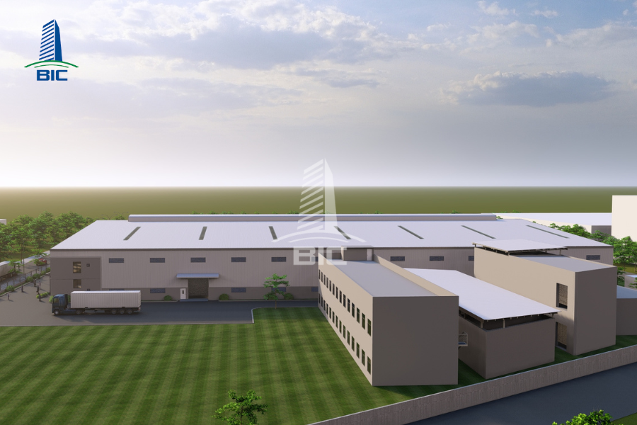
The 1:500 master site plan is the primary document illustrating the precise locations of individual project components within the actual land boundaries. This drawing identifies the positions of the main production workshop, raw material warehouse, finished goods warehouse, administrative office building, transformer station, and centralized wastewater treatment facility. In addition, the master planning drawings establish carefully organized internal traffic routes, completely separating incoming raw material transportation routes, finished goods dispatch traffic, pedestrian walkways for workers, and access routes for firefighting vehicles during emergencies. A scientifically organized transportation network minimizes operational conflicts, ensures workplace safety, and improves factory production efficiency.
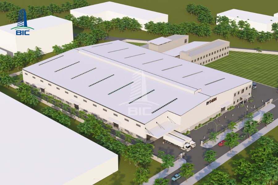
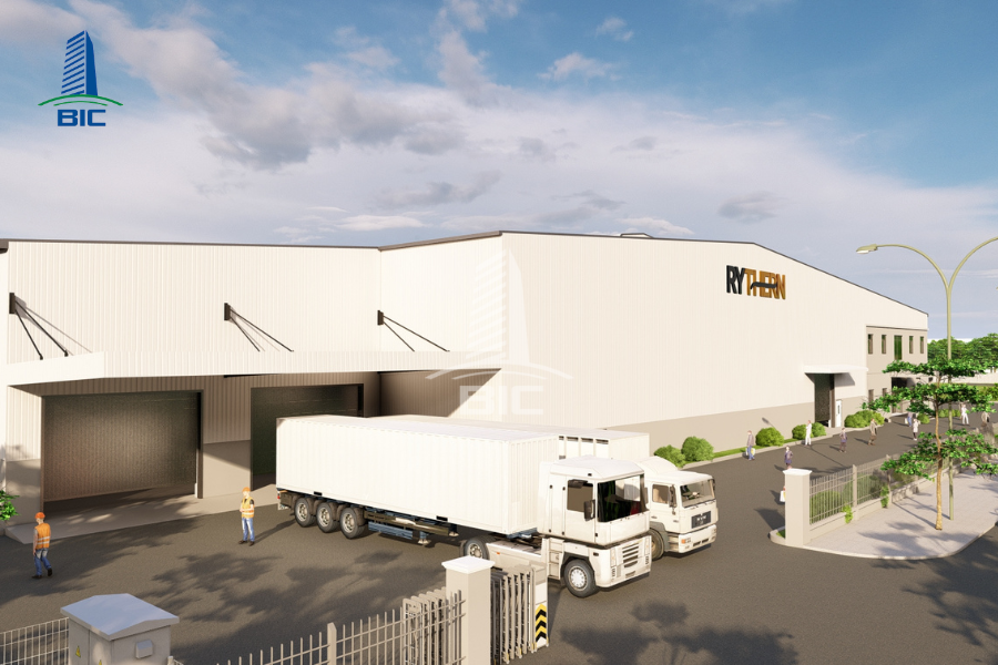
Floor plan drawings provide detailed information about the functional arrangements of each floor, internal workshop dimensions, structural column grid spacing, and boundaries between production operating areas. Supporting spaces, including technical control rooms, employee rest areas, consumable material storage rooms, and industrial restroom facilities, are also arranged efficiently. Building elevation drawings illustrate the overall architectural form, factory floor heights, locations of loading and unloading roller shutter doors, personnel entrances, and ventilation and daylighting windows. Longitudinal and cross-sectional drawings are essential for identifying factory clear heights, roof ridge elevations, metal roofing slopes, and technical connections between load-bearing steel columns and roofing systems. These specifications enable factory design consultants to accurately determine spatial capacity and accommodate overhead crane systems or large-scale production machinery.
Architectural finishing drawings specify the technical requirements and construction details for individual building surfaces. The documentation includes detailed specifications for heavy-duty, hardened epoxy flooring systems, as well as dust-resistant and chemical-resistant floor coatings for specialized production areas. For the building envelope, drawings accurately specify the thickness of insulated wall panels, fire-resistant partitions, and heat-insulated metal roofing systems combined with natural daylighting panels to reduce daytime lighting energy costs. In addition, architectural documentation within the construction design process specifies exterior finishing materials, dust-resistant coating systems, and colors reflecting the company's brand identity. BIC's thorough preparation of architectural finishing drawings enables investors to control material quality, maintain architectural consistency, and improve building durability.
The structural engineering discipline establishes the primary load-bearing framework of the entire factory, ensuring stability, durability, and resistance to mechanical forces and natural disasters.
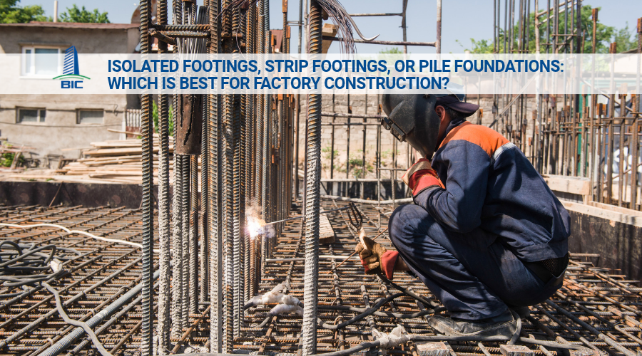
Foundation drawings provide detailed information about the locations, geometric dimensions, and reinforcement arrangements of isolated footings, strip footings, or reinforced concrete pile foundations based on actual geotechnical investigation data. For factories equipped with stamping production lines, precision machining equipment, or machinery generating substantial dynamic loads, the drawings separately illustrate specialized machine foundation pits and vibration isolation solutions. In addition, foundation documentation includes structural details for underground fire water storage tanks, septic tanks, and factory floor drainage channels, ensuring coordinated load-bearing performance throughout the project.
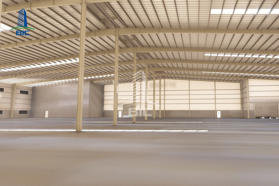
Pre-engineered steel frame drawings play a central role in creating large-span production spaces. The documentation provides detailed dimensions for load-bearing steel columns, steel beams and rafters, roof purlins, and wall girts. To ensure overall structural stiffness and improve resistance to severe storms, factory design consultants must accurately calculate and illustrate roof bracing, column bracing, and purlin bracing systems. These engineering calculations help minimize structural deformation caused by wind loads and the operational loads of overhead cranes installed inside the factory.
Steel fabrication drawings provide detailed information about the geometry of individual components, connection plate thicknesses, weld specifications, and structural steel section types used for each beam and column. These documents are accompanied by enlarged drawings of critical load-bearing connections, including anchor bolt connections between foundations and column bases, column-to-rafter connections, and secondary beam connections. These connection details determine the building's ability to withstand tensile forces, compressive forces, and bending moments. Accurate representation of these structural connections enables the general construction contractor to carry out steel fabrication and on-site erection safely and precisely.
MEP infrastructure functions as the circulatory and nervous systems of the factory, maintaining continuous operation of production lines and supporting employees' daily activities.
Electrical design drawings include power distribution schematic diagrams, locations of internal transformer stations, backup generators, and main distribution switchboards. Layout drawings precisely illustrate electrical cable ladder and tray routes, wiring networks, locations of high-load industrial power outlets, and energy-efficient lighting systems for individual production areas. In addition, the drawings clearly specify electrical safety grounding systems and lightning protection grounding arrangements for the entire factory building.
Water supply and drainage drawings include network diagrams for domestic water supply, industrial process water supply, and roof stormwater drainage systems. MEP engineers must calculate appropriate pipe dimensions and drainage slopes to prevent roof drainage overflow or water accumulation. For industrial wastewater, the drawings provide detailed layouts of internal wastewater collection pipelines connected to the industrial wastewater treatment facility. The wastewater treatment process diagram is designed to ensure that treated effluent meets applicable environmental standards before being discharged into the shared collection system.
For manufacturing factories, HVAC drawings include plans and sections illustrating ventilation and cooling systems, air ducts, industrial exhaust fans, and negative-pressure evaporative cooling pads. Factories requiring specialized environmental conditions will also include cleanroom design drawings and temperature and humidity control solutions. In addition, the documentation illustrates compressed air pipeline routes from the central compressor station to individual production machines, ensuring stable and safe compressed air pressure throughout factory operations.
Fire prevention and fighting systems and environmental protection documentation are mandatory components supporting legal compliance and the facility's ability to respond effectively to emergencies.
Fire protection drawings provide detailed layouts of firefighting water supply pipelines, dedicated fire pump stations, and wall-mounted fire hose connections. Automatic sprinkler systems are designed with sprinkler head spacing and distribution densities that comply with applicable fire protection regulations. In addition, the drawings specify the locations of automatic smoke detectors, heat detectors, and central fire alarm control panels. Fire compartmentation solutions, including specialized fire-resistant walls and fire-resistant coating systems for load-bearing steel structures, are also illustrated in detail.
Emergency evacuation drawings clearly identify the shortest designated escape routes for workers during fire or explosion incidents. The documentation provides detailed locations of exit signs, emergency lighting, fire-rated doors, and external emergency staircases. On the master site plan, fire protection drawings establish access roads surrounding the factory with appropriate widths and vehicle turning radii, ensuring that specialized firefighting vehicles can easily reach all necessary areas of the facility.
Environmental infrastructure drawings provide detailed designs for hazardous waste storage areas and general industrial waste warehouses that are completely separated from production zones. Acoustic insulation and vibration reduction solutions for high-capacity equipment, along with industrial dust extraction and exhaust gas treatment systems, are also fully illustrated through detailed technical drawings. These systems help ensure that the factory does not release hazardous substances into the surrounding natural environment.
Effective coordination among specialized design disciplines is a decisive factor in determining the quality, safety, and implementation schedule of an entire industrial construction project.
BIC, as a general construction contractor, applies three-dimensional Building Information Modeling (BIM) technology to integrate all architectural, structural, MEP, and fire protection drawings into a unified 3D model. The software automatically checks and identifies technical clashes, such as steel beams conflicting with fire protection pipelines or electrical cable ladders and trays interfering with ventilation ducts. Thoroughly resolving these conflicts within the digital environment ensures the highest level of drawing accuracy at handover and prevents demolition and corrective work during on-site construction.
Using the coordinated construction design drawings, BIC's cost estimation team prepares detailed material quantity takeoffs in the Bill of Quantities (BOQ). Accurate quantity takeoffs based on coordinated drawings enable investors to understand the projected budget clearly and eliminate the risk of additional costs beyond the agreed contract. BIC also provides consulting on optimized material solutions that balance initial capital expenditure (CAPEX) with long-term maintenance and operating costs.
Under the turnkey Design and Build model, BIC assumes comprehensive responsibility for developing factory design proposals, obtaining fire protection design approvals, applying for construction permits, and organizing on-site construction activities. Consolidating responsibilities under a single point of contact improves technical coordination, shortens project preparation time, and supports the commitment to handing over the completed facility according to the agreed schedule.
A complete set of factory design drawings requires close coordination among architecture, structural engineering, MEP infrastructure, and fire protection disciplines. Comprehensive and coordinated technical documentation not only ensures building safety and architectural quality but also optimizes functionality and improves investment capital efficiency. Partnering with BIC as a general construction contractor provides investors with integrated solutions covering construction design documentation, fire protection regulatory approval, and turnkey construction, ensuring that factories can quickly commence efficient and sustainable production operations.