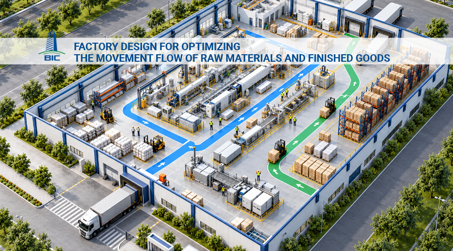
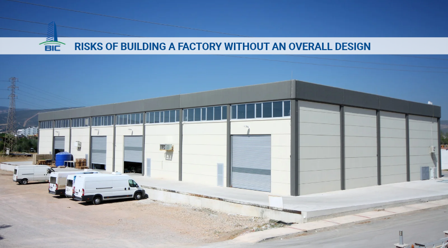
Factory structural design determines the load-bearing capacity, stability, and service life of a building throughout its operation. The structural system not only carries the weight of the roof, walls, and the building itself, but must also meet the loads from machinery, goods, transport vehicles, overhead cranes, and environmental impacts.
In practice, insufficient data on equipment loads, geotechnical conditions, or expansion plans can lead to settlement, cracking, vibration, and deformation. Conversely, increasing member sizes or using more materials without a calculation basis will raise costs without necessarily improving usage efficiency.
Therefore, the structural solution must be developed in parallel with factory design, the production line, and technical systems. In the article below, BIC analyzes the data investors need to prepare, the load groups that must be considered, and foundation, load-bearing frame, and material solutions that help ensure building durability.
Structural design is not only intended to ensure that the building stands safely, but also to maintain stability, usability, and service life under actual production conditions.
Factory structural design is the process of determining how load-bearing components receive and transfer loads to the ground. Based on functionality, machinery, and site conditions, engineers select materials, member sizes, connection systems, and technical requirements.
The results are presented in the construction design dossier, serving as the basis for quantity takeoff, component fabrication, and construction organization.
The structural system begins with the building foundation, machine foundations, and the factory floor or slab. The superstructure includes columns, beams, rafters, purlins, bracing systems, and connections.
For factories with overhead cranes, the system also includes column corbels and crane runway beams that carry dynamic loads. Buildings with mezzanines or auxiliary areas must include suitable floor structures and supporting systems according to their functions.
Load-bearing capacity reflects the safety of structural members under applied loads. Stiffness relates to deflection, displacement, and vibration during use. A member may not have lost its load-bearing capacity, but it can still affect operation if deformation is excessive.
Long-term durability also depends on humidity, chemicals, temperature, corrosion, and maintenance accessibility. Therefore, the fact that a structure does not fail immediately is not enough to conclude that the building adequately meets long-term usage requirements.

The accuracy of factory structural design depends directly on the quality of input data. If information about machinery, loads, or geotechnical conditions is incomplete, the design unit must use assumptions. Assumptions that are too low create safety risks, while assumptions that are too high increase member sizes and investment costs.
Investors need to define the expected length, width, usable height, number of floors, mezzanines, span, and column spacing. These parameters determine the working scheme of the structural system and directly affect internal forces, deflection, and material quantities.
Door locations, loading and unloading areas, forklift routes, and column-free space requirements also need to be provided. If only the area is defined without clarifying production organization, the structural solution may obstruct the production line or require adjustment after calculations have already been completed.
Required information includes more than just the dimensions and total weight of the machine. The design unit must also know the center of gravity, load transfer points, operating loads, vibration levels, anchor bolts, and machine foundation requirements.
Equipment with the same weight but different contact areas will create different pressures on the floor. Press machines, rotating machines, or moving equipment also generate dynamic effects that static loads do not fully reflect. Therefore, investors should provide equipment drawings and specifications from the manufacturer before finalizing the foundation and floor design.
Warehouse loads depend on the type of goods, stacking height, rack structure, and goods distribution. Storage racks create concentrated loads at rack legs, while goods stored directly on the floor may distribute loads over a wider area.
Forklifts and transport vehicles create moving loads and repeated impacts on the floor and joint areas. Defining operating routes, wheel loads, and usage frequency helps properly design floor thickness, reinforcement details, and surface solutions.
Nominal lifting capacity alone is not sufficient to design the column system and crane runway beams. The dossier needs span, lifting height, crane self-weight, wheel loads, travel speed, and working frequency.
An overhead crane generates both vertical and horizontal loads during acceleration, braking, or load movement. These repeated effects influence the stiffness, connections, and durability of the structure. Specifications should be coordinated with the crane supplier before determining corbel elevations and runway beam sizes.
The foundation solution must be based on a geotechnical survey conducted at the exact construction location and should not be inferred from nearby buildings. Soil composition, bearing capacity, settlement, and groundwater level directly affect the selection of shallow foundations, pile foundations, or ground treatment solutions.
The production environment must also be clearly described. High humidity, chemicals, heat, dust, or corrosive vapors can gradually degrade materials and connections over time. These data are the basis for selecting materials, protective coatings, and suitable inspection cycles for the building.

A factory structure does not only carry its own self-weight. It also receives many effects that vary according to function, equipment, and environmental conditions. Each load group has different force transfer characteristics. If a load is omitted or applied incorrectly, the calculation results may not accurately reflect the operating condition of the building.
Permanent loads include the weight of foundations, columns, beams, rafters, purlins, roofing, wall cladding, and finishing layers. Fixed equipment, pipelines, cable trays, ceilings, and long-term suspended systems must also be included in the appropriate load group.
Although they change little during use, permanent loads act continuously on the structure and ground. Underestimating the weight of suspended equipment can increase roof deflection, while overly conservative assumptions can make members heavier and increase unnecessary costs.
Imposed loads come from people, machinery, goods, storage racks, forklifts, and production activities. Load values and distribution depend on each area. Office floors, warehouses, and machine areas cannot use the same load assumption.
Storage racks usually transfer forces through concentrated rack legs, while goods placed directly on the floor create loads over a wider area. Investors need to clearly define locations, storage heights, and possible functional changes so the design does not become underloaded when the layout is rearranged.
Wind creates pressure on windward surfaces and suction on roofs, walls, and edge zones. For factories with large roof areas, roof uplift and horizontal force transfer through bracing systems must be fully checked.
Rainwater can increase roof loads if drainage is restricted or ponding occurs on the surface. Temperature changes also cause members to expand and contract, especially in long buildings. These effects influence connections, movement joints, and the tightness of the building envelope.
Press machines, rotating machines, motors, and moving equipment generate forces that change over time. If only the static weight of the machine is used, the design may not reflect vibration transmitted to the foundation and nearby areas.
Overhead cranes create vertical wheel loads, horizontal forces during travel, and impacts during acceleration or braking. Forklifts also create repeated loads on the floor, especially at turning areas and joints. Dynamic effects must be considered together with operating frequency because they can affect connections and the long-term durability of the structure.
Loads do not occur independently in reality. At a given moment, a factory may simultaneously carry self-weight, goods, crane operation, and wind effects. Therefore, engineers must consider appropriate combinations for each working condition.
One group of combinations is used to check safety and load-bearing capacity. Another group is used to control deflection, displacement, vibration, and normal usability. A structure that is strong enough but deforms excessively can still cause roof leakage, crane rail misalignment, or unstable machinery operation.
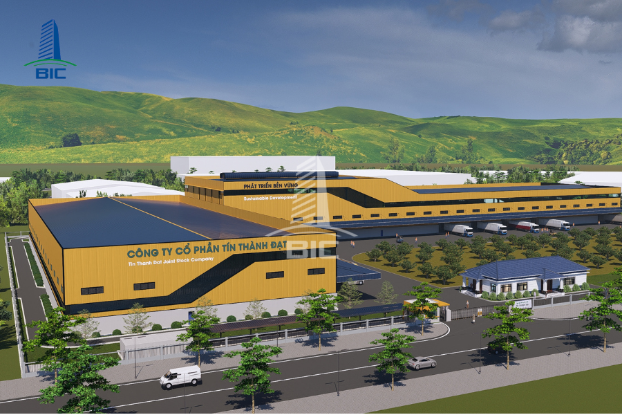
The structural system must be selected based on function, loads, site conditions, and operating plans. Automatically applying a familiar solution can make it difficult to arrange the production line, increase foundation costs, or create material protection requirements during operation.
Steel frames are suitable for factories that require large spaces, fewer columns, and fast erection schedules. Components can be fabricated in a workshop before being transported to the site, helping control dimensions and organize construction by area. Their relatively light self-weight can also reduce loads transferred to the foundation.
However, steel structures are slender, so stability, deflection, and displacement must be checked, not only load-bearing capacity. Humid environments or environments with chemicals or corrosive vapors require suitable surface protection solutions. Requirements for fire resistance, weld inspection, bolts, and protective coating maintenance must also be defined from the design stage.
Reinforced concrete has high stiffness and is often considered for multi-storey factories, areas with heavy equipment, or buildings requiring vibration control. This material is also convenient when columns, beams, and slabs need to work together as a continuous load-bearing system.
In return, its high self-weight increases foundation requirements. Construction requires time for formwork, reinforcement, concrete pouring, and curing. If not properly controlled, shrinkage, cracking, or member misalignment can affect durability and machinery installation.
A project may use reinforced concrete columns or multi-storey blocks, while using steel structures for large-span roof areas. This combination allows materials to be selected according to the specific requirements of each zone instead of applying one system to the entire building.
The key point to control is the transition between different structural types. Differences in stiffness, deformation, construction sequence, and force transfer must be clearly calculated. Unsuitable connections can create local stress concentrations or cause difficulties during erection.
Steel frames are not always more economical, and reinforced concrete is not automatically more durable in every environment. Options should be compared based on the same requirements for function, durability, construction time, maintenance, and expansion capacity.
Investors should require the design unit to explain the basis for selection, main quantities, and the impact of each option on foundations, technical systems, and schedule. This approach helps select a structural system based on overall effectiveness instead of only material unit prices.
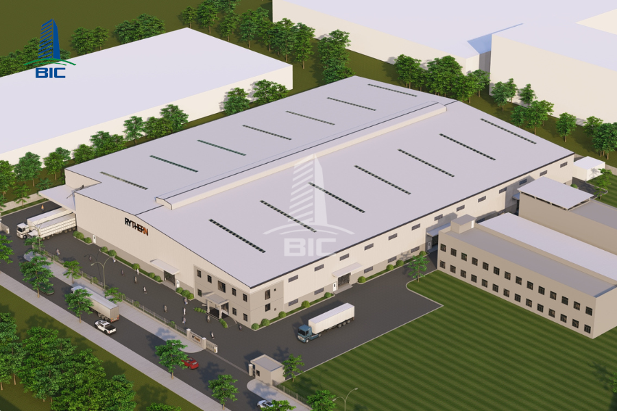
Foundations and floors receive almost all loads from the building and production activities. Mistakes in these two items are often difficult to correct after machinery has been installed. Therefore, the solution must be defined based on geotechnical conditions, loads, and actual usage requirements, not only on factory area.
Isolated footings or strip foundations may be suitable when the bearing soil layer is at a favorable depth and settlement can be controlled. Raft foundations are considered when loads need to be distributed over a large area, while pile foundations are often used to transfer forces to better soil layers when upper soils are weak or building loads are large.
The selection cannot be based only on the structural type above. The same factory model built on two different sites may require completely different foundation solutions. The geotechnical survey report must provide sufficient data at the project location so engineers can evaluate bearing capacity, settlement, and groundwater conditions.
A building may tolerate a certain total settlement, but can still be seriously affected if settlement varies between locations. Differential settlement changes column elevations, causes wall cracking, frame deformation, and crane rail misalignment. Machinery requiring high precision may also operate unstably.
The design needs to consider differences between the factory area, heavy-load warehouse, office block, and yards. Ground treatment methods, filling sequence, compaction, and elevation monitoring during construction must be coordinated to reduce differential deformation.
Factory floors may carry loads from machinery, storage racks, forklifts, and goods placed directly on the floor. Each type transfers force differently, so one common floor thickness should not be applied to the entire layout.
The design unit needs to zone load areas, define subgrade build-up, concrete thickness, reinforcement, and joint locations. Expansion joints and construction joints must be arranged according to forklift travel directions to reduce edge chipping. Requirements for abrasion resistance, dust control, or chemical resistance must also be defined according to production activities.
Equipment with concentrated loads, vibration, or strict elevation requirements often needs separate foundations. Machine foundations must receive operating loads, control vibration, and limit effects transferred to the floor, structure, and nearby equipment.
Information on machine leg positions, anchor bolts, dynamic forces, and installation requirements must be obtained from the supplier. If machine foundations are constructed before equipment is finalized, even small deviations in dimensions or elevation can lead to drilling, cutting, reinforcement, and technical system adjustments.
Rainwater or production water seeping into the ground can change soil conditions, cause local erosion, or reduce the quality of the subgrade. Land leveling elevations, surface slopes, collection channels, and drainage systems must be designed in coordination with foundations and factory floors.
Underground pipe routes need to be defined in advance to avoid crossing pile caps or heavy-load areas. When a pipe is damaged under machinery or heavy-load floors, repair becomes complicated and may interrupt production.
The main frame, bracing system, and connections must be calculated as one unified system. Columns or rafters that are individually strong enough do not guarantee building stability if the load path is discontinuous or connections do not behave according to design assumptions.
Column positions need to be determined together with production lines, machinery, storage racks, and vehicle routes. A poorly located column can reduce usable area, obstruct forklifts, or force the business to adjust the production layout.
Increasing column spacing creates more open space, but also increases the loads on beams, rafters, and purlins. Conversely, placing too many columns may reduce the quantity of each member but create operational inconvenience. A suitable option must balance space efficiency and the cost of the entire structural system.
Beams and rafters receive loads from the roof, suspended equipment, and technical systems, then transfer them to columns. In addition to load-bearing capacity, the design must control deflection. Excessive deformation can alter roof slopes, cause water ponding, or affect pipelines and suspended equipment.
Member splice locations should suit fabrication, transportation, and erection capacity. If the factory has an expansion plan, the edge frame details should also be studied so extension can be carried out without excessive demolition or reinforcement.
Roof bracing and column bracing create load paths for horizontal loads while maintaining frame stability during use. Bracing also plays an important role during erection because an incomplete frame may behave differently from its final design state.
Bracing locations must be coordinated with doors, walkways, machinery, and pipelines. Arbitrarily removing or relocating bracing to make room for equipment can change the load-bearing scheme of the entire building. Any adjustment must be checked by the design unit before implementation.
Bolted connections, welds, connection plates, and anchor bolts transfer forces between members. Even when main member sizes are correct, inadequate connections can still create weak points in the structural system.
Connection details must reflect the assumptions in the calculation model and suit fabrication and construction conditions. Locations that are difficult to weld, difficult to tighten, or impossible to inspect after installation must be resolved on the drawings. Fabrication quality and erection tolerances must also be controlled because they directly affect force transfer capacity.
An overhead crane transfers loads through its wheels to crane runway beams, corbels, columns, and foundations. In addition to lifting loads, the structural system also carries crane self-weight, horizontal forces during travel, braking effects, and repeated loads during operation.
The stiffness of columns and runway beams must be controlled to maintain the elevation, spacing, and straightness of the rails. Excessive deformation can cause uneven wheel movement, increase wear, and affect operation. Therefore, structural design for factories with overhead cranes must coordinate early with the equipment supplier regarding wheel loads, span, lifting height, and duty class.
Structural durability does not depend only on material strength at the time of handover. Moisture, chemicals, temperature, and dust can degrade materials during operation. The design must correctly identify deterioration agents, select protective solutions, and create conditions for periodic inspection.
Corrosion reduces the cross-sectional thickness and working capacity of steel members. The deterioration rate depends on humidity, chemicals, dust, water accumulation, and ventilation. Therefore, the same frame system used in two different production industries may require different protection solutions.
Paint or coating systems must be selected according to the environment and expected service life. Protection effectiveness depends not only on coating material, but also on surface preparation, coating thickness, and workmanship quality. Structural details should reduce narrow gaps, water-retaining areas, and locations that are difficult to clean or repaint.
Cracks can form due to loads, shrinkage, temperature changes, or construction processes. Some cracks do not immediately make the member unsafe, but they create paths for water and chemicals to penetrate, causing internal reinforcement corrosion.
Solutions should include material selection, reinforcement arrangement, joint details, and control of concrete pouring, compaction, and curing. In areas exposed to wastewater or chemicals, the surface must have suitable protection layers. Cracks should be monitored for location, width, and development to identify the cause before repair.
High temperatures change material properties and cause deformation due to expansion. If a heat source is concentrated near columns, beams, or connections, local effects can be much greater than the general temperature of the factory.
The design unit needs to determine operating temperature, distance to heat sources, and duration of exposure. Only then can protective materials, insulation layers, or structural separation from equipment be selected. It should not be assumed that steel or concrete structures can operate stably under all thermal conditions.
A durable member that cannot be accessed will be difficult to inspect and maintain at the right time. Locations such as roofs, gutters, column bases, bracing systems, connections, and crane runway beams need suitable access.
The handover dossier must accurately show materials, protective layers, and the as-built condition. Investors need to develop an inspection plan based on environmental exposure and the importance of each member. Early detection of coating peeling, water leakage, cracking, or deformation usually allows simpler treatment than repair after damage has spread.
Structure cannot be designed separately from other disciplines. Column positions, beam elevations, equipment loads, and openings directly affect functionality. If coordination is only carried out after drawings have been completed, adjusting one member may lead to changes across multiple systems.
The column grid must be checked together with machinery positions, production lines, storage racks, and transport flows. A column that does not affect architectural calculations may still obstruct operations, narrow forklift routes, or occupy space needed for equipment maintenance.
Building foundations and machine foundations also need to be arranged simultaneously. If the two foundation systems intersect or are too close to each other, force transfer and construction sequencing become more complex. Locations where machines may be added in the future should be identified so floors and installation spaces can be properly prepared.
Cable trays, pipelines, fans, air ducts, and suspended equipment all add loads to roofs or floors. Their weights, support locations, and maintenance methods must be provided to the structural engineer before calculations are finalized.
Openings through beams, slabs, or load-bearing walls must be shown in the dossier and checked from the beginning. Arbitrary drilling or cutting of members on-site can remove reinforcement, reduce cross-sections, or change load paths. When new requirements arise, the design unit must evaluate them and propose reinforcement solutions if necessary.
Beam deflection, column displacement, and roof deformation affect walls, doors, glass, metal cladding, and waterproofing joints. A structure may remain safe, but unsuitable displacement can make doors difficult to operate, cause wall cracking, or create roof leakage points.
Architectural drawings need to be checked together with envelope connection details and movement joints. Finishing components must be able to accommodate expected structural displacement without damage.
The factory expansion direction must be defined during the initial design stage. Edge frames, bracing systems, foundations, and building envelope at connection locations should be arranged so they can be dismantled or extended with reasonable intervention.
If the intended expansion zone is occupied by technical stations, underground pipelines, or difficult-to-relocate bracing systems, the business may need to renovate many items before building additional areas. An expansion plan is only effective when it is coordinated across structure, master layout, and technical system capacity.
Structural cost is formed by material quantities, member complexity, construction conditions, and protection requirements during use. Construction area is only an initial data point and is not enough to determine the budget for foundations and load-bearing systems.
Height, span, column spacing, and roof shape directly affect internal forces and member sizes. Large-span factories help reduce internal columns, but usually require larger beams or rafters to control load-bearing capacity and deflection.
Buildings with complex layouts, multiple elevations, or many transition areas require additional members and connections. Meanwhile, simple geometry and a reasonable column grid are usually more favorable for design, fabrication, and erection.
Machinery, goods, storage racks, mezzanines, and overhead cranes change the requirements for floors, foundations, columns, and beams. The heavier or more concentrated the load, the more carefully the members and load transfer solution must be considered.
Expansion capacity also affects cost. If the investor requires the current structure to reserve capacity for future loads, the additional investment must be based on a specific plan to avoid overdesign across the entire building.
Good geotechnical conditions may allow the use of shallow foundations with a relatively simple construction process. Conversely, weak soils, deep bearing layers, or large settlement may require ground treatment, pile foundations, and more complex control measures.
Foundation costs can only be evaluated reliably when survey data from the actual site are available. Using unit rates from another project can create major discrepancies because geotechnical conditions are different.
Steel type, concrete grade, bolts, welding materials, and surface protection layers all affect cost. A factory in a humid or chemical environment may require more suitable surface treatment and coating systems than a building in normal conditions.
Low initial cost with fast material deterioration will increase maintenance and repair needs. Investors should evaluate service life, availability, and long-term usage cost when selecting options.
Two factories with the same area but different spans, heights, machine loads, overhead cranes, or geotechnical conditions will have different structural quantities. Square-meter unit rates do not fully reflect differences in foundations, floors, connections, and material protection requirements.
Preliminary unit rates can be used to form an initial budget. When selecting a solution or contractor, investors need to compare based on the same technical dossier, work scope, and material standards to avoid underestimating an incomplete quotation.
A structural design unit does not only perform calculations. It must also understand production functions, fabrication conditions, and how the building will be erected. Investors should evaluate capability based on personnel, similar projects, and control processes instead of only comparing design fees or total construction prices.
Experience should be considered according to production industry, loads, structural type, and project complexity. A unit that has designed standard warehouses may not necessarily have sufficient experience with factories that include overhead cranes, vibrating machines, or corrosive environments.
Investors should request similar project records and clarify the scope the unit performed. Photos of completed projects are only for reference if they do not show the unit’s responsibility in design, fabrication, or construction.
The structural solution must be coordinated with architecture, MEP, fire prevention and fighting, infrastructure, and production lines. If disciplines work separately, conflicts often only appear during detailed drawing development or construction.
A capable coordination team will check suspended equipment loads, opening locations, pipeline routes, and installation clearances before finalizing members. This helps reduce drilling, cutting, reinforcement, and adjustments on-site.
A good option must clearly state input data, load assumptions, and the reasons for selecting the structural system. Investors do not need to directly check all calculations, but they should receive a clear explanation of why certain spans, column spacing, materials, and foundation solutions are chosen.
If a unit only presents low quantities without clarifying deflection, stability, maintenance capacity, and expansion potential, the solution does not yet have enough basis for evaluation. Material optimization must go together with usability and building durability.
The dossier must be internally checked before issuance and coordinated with related disciplines. During construction, materials, member dimensions, welds, bolts, elevations, and erection sequence must be controlled according to approved drawings.
For general construction contractors, investors need to evaluate both subcontractor management capability and the document storage system. A correct design that is fabricated or erected incorrectly will still reduce the effectiveness of the entire structural system.
Structures may need to be checked when the business adds machinery, increases warehouse loads, or installs additional overhead cranes. A unit that understands the original dossier will have a stronger basis for quickly evaluating the impact of changes.
Investors should prioritize units with a process for receiving post-handover requests, supporting existing condition checks, and updating records. This support capability helps maintenance, renovation, and expansion be carried out using reliable technical data.
Factory durability is not determined by increasing member sizes or using more materials. An effective solution must begin with accurate data on geotechnical conditions, machinery, goods, overhead cranes, and the production environment. Based on these data, the design unit can select suitable structural systems, foundations, materials, and protection solutions.
Factory structural design must also be coordinated simultaneously with the production layout, architecture, and MEP systems. Controlling drawings, fabrication, erection, and maintenance helps the building maintain load-bearing capacity, stability, and operating conditions in the long term.
BIC provides factory design, construction design, and general construction services according to the actual requirements of each project. Investors can contact BIC for site surveys, load analysis, and consulting on structural solutions suitable for the company’s functionality, budget, and development plans.