In the construction of steel structure workshops, bolts are always used. For high-strength bolted connections between the foundation and connecting members to each other, bolts are formed through friction between them. High strength bolts can be grade 8.8 bolts; 10.9 or even better bearing bolts.
During the installation process, tightening creates a pre-tension in the bolt, resulting in the steel plates being pressed tightly against each other and creating a large frictional force against the shear force in the connection.

The resistance that each friction surface of the connected steel members can withstand when tightening high-strength bolts is calculated as follows:
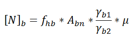
In there
fhb - calculated tensile strength of high-strength bolts, fhb = 0.7*fub
fub - standard bolt breaking strength, for bolts of grade 8.8 and 10.9 80 kN/cm2 and 100 kN/cm2 respectively
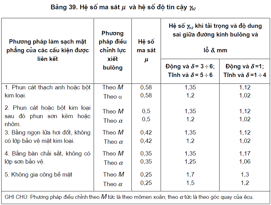
µ - coefficient of friction, taken from the table below
b2 - reliability coefficient, taken from the table below
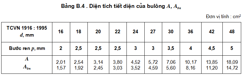
Abn - real area of bolts, taken from the table below
γb1 - coefficient of working condition of the connection, depending on the number of bolts in the connection, = 0.8 if the number of bolts is less than 5; = 1 if the number of bolts is greater than or equal to 10; = 0.9 for the other case
The number of bolts in the connection when subjected to axial force N is determined by the formula
.png)
Where nf is the number of friction faces of the connection, c = 1
Tensile force in bolt body due to tightening ecu P = fhb*Abn
Lookup tables
Torque
The value of tightening torque depends on the bolt diameter, the tension in the bolt body, is determined as follows:
M = k * P * EASY
Where P and D are the tension in the bolt body (see above) and the diameter of the bolt. k is the empirical coefficient = 0.12 to 0.2
The tightening torque can be controlled with a dedicated Wrench (force wrench)
In case the column is subjected to moment M and shear Q:
- the shear force Q you can divide evenly by the number of bolts, each bear a part.
- bending moment: this is quite complicated, depending on the column cross-section, bolt arrangement, column foot cipher thickness, how to reinforce ciphertext around bolt position,...
Typical case of an H-section column subjected to bending in the web: you have to find the area of compression on the concrete base of the column, balance it with the tension in the bolt, then determine the swing arm and then find the resisting moment. curling. This method requires solving the quadratic equation to find the area of the compression zone of the base plate on the concrete foundation.
If you assume the swingarm is from the center of the column to the row of compression bolts, then this assumption is usually in favor of safety, not savings.
It is necessary to pay attention to the thickness of the ciphertext, if the ciphertext is thin and not properly reinforced, it will be deformed a lot, the effect of the concrete arm acting on the ciphertext will appear -> increasing the tensile force. in bolt...
In general, the problem is not simple, you should read more foreign references for more clarity.
After determining the shear and tensile forces in the bolt, check according to the conditions in TCVN.
In theory, as you say NBG and AISC do the same and I also follow AISC.
According to TCVN: - Foundation bolts are not cut
According to TC some other countries: (for example, the US), bolts are expected to bear both shear and tensile forces.
- If you scale 0407 according to AISC, then search AISC's design Guide 1, solve the quadratic equation and find the solution of the neutral axis position.
- If you follow the TCVN, you follow the way of the steel project book, save a lot of debate.
Both of the above methods must follow the formulas in the book, which are quite long, and cannot be elaborated on the forum. You should find books to read and follow, you will find many other things.
The arrangement of bolts must ensure the requirements of good power transmission, simple structure and easy fabrication!
1. The distance between the centroids of two bolts or studs in any direction is taken as follows:
1.1. Smallest
+ Bolts: 2.5d
+ Rivet: 3d
1.2. The maximum, in the edge studs when there is no edge angle steel for tension and compression members is 8d or 12t.
1.3. Largest, in the center and edge studs when rim angle steel is present:
+ CK in compression: 12d or 18t
+ CK tensile: 16d or 24t
2. Distance from the center of the bolt or rivet to the edge of the member
2.1. Minimum along force: 2d
2.2. Minimum perpendicular to force
+ When the edge of the steel plate is cut: 1.5d
+ When the edge of the steel plate is rolled: 1.2d
2.3. Biggest 4d or 8t
2.4. Min, for high strength bolts when any edge in any direction 1.3d
Where: d is the bolt hole diameter and t is the outer thinnest plate thickness.