In the construction field, construction design drawings play an extremely important role, considered the method of fully conveying the ideas and construction plans for factory construction projects. This serves as a database detailing the shape, structure, and technical systems within the project, helping the construction team execute according to technical standards, ensuring quality and safety during construction. Let's explore the details of construction design drawings with BIC in the article below.
A construction drawing (also known as a technical design drawing or a construction drawing) is an important type of technical document in the construction industry, used to represent the detailed shape, structure, dimensions, materials, and construction methods of a project.
Simply put, a construction drawing is like the skeleton of a project, helping to outline the entire project from idea to reality, ensuring that construction is carried out accurately to the millimeter.
The Role of Construction Drawings:
- Serves as a basis for engineers and construction teams to understand and execute correctly according to technical specifications.
- Fully presents parameters and visual images, helping the construction process run smoothly and minimizing errors.
- Serves as a legal document for obtaining construction permits, appraising construction designs, and accepting completed projects.
Instead of hand-drawing as in the past, current drawings are designed using specialized software such as AutoCAD, Revit, SketchUp, etc., computer-aided to ensure absolute accuracy, easy editing, and long-term storage.

In a construction project, the design drawing serves as the foundation for conveying the complete design ideas for the factory, construction parameters, and operational methods of the project. Typically, a construction drawing will include detailed drawings related to architecture, structure, electrical and plumbing systems, construction technology, and how the building will be used in the future.
Currently, factory construction drawings are divided into two main groups as follows:
This is an indispensable set of documents when applying for a legal factory construction permit. This set of factory design drawings helps authorities assess whether the project complies with planning regulations and technical standards. The basic components of a construction permit drawing include:
- Floor Plan: Shows the overall layout of rooms and functional areas within the building as viewed from above. This is a diagram simulating the location of spaces such as offices, work areas, warehouses, security booths, canteens, restrooms, etc., linked to other technical drawings.
- Elevation Drawings: Shows the external appearance of the building as viewed from different directions such as front-back, left-right. This drawing helps the investor clearly visualize the design style, balanced proportions, and overall perspective of the factory.
- Section Drawings: Provide an overall view of the internal structure of the factory by cutting vertically or horizontally along an axis. From the section drawings, the investor can easily determine the floor height, staircase location, window dimensions, wall thickness, and layout of details in the factory's work areas.
- Site Plan: Identifies the specific location of the land plot and the building within the overall construction area, ensuring compliance with local planning regulations.
- Drawing Title Block: Contains basic information such as the project name, investor name, factory design company, design date, drawing scale, etc.
- Elevation Drawings: A flat projection showing the entire exterior of the building from a fixed direction, helping to clearly observe the structure and perspective of the factory's exterior.
- Location Plan / General Layout: Shows the overall layout of the building on the land plot, along with information on zoning and elevation through various related drawings.
- Title Block in Construction Drawings: The title block is located in the lower right corner of the drawing, containing information such as the project name, drawing title, design unit, etc. The outer frame is drawn with a bold line, spaced from the edge of the standard paper according to the paper size for convenient management and storage.

A construction design drawing includes architectural drawings, structural details, load-bearing structures, and the electrical and plumbing systems of the project.
- As-built drawings: Created during construction or upon completion of the project to accurately reflect actual changes made compared to the original design. Adjustments are noted in red ink.
- Assembly drawings: Illustrate how the different parts of the project connect to each other through plans, elevations, and 3D projections.
- Site plan drawings: Determine the location of the project on a survey map, describing boundaries, roads, and related elements, typically at a scale of 1:2500, 1:1250, or 1:500.
- Component detail drawings: Explain the dimensions, tolerances, and technical specifications of each part of the project, shown at a large scale such as 1:10, 1:5, 1:2, or 1:1.
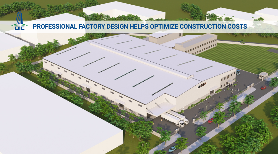
Cost is always a crucial factor determining the implementation of a construction project. Through design drawings, investors can determine whether construction costs are in line with the initial budget. In addition, the drawings can provide advance estimates for related expenses such as building materials, technical equipment, and labor, making the financial preparation process more proactive. Without drawings from the beginning, construction is easily interrupted due to unexpected cost overruns, affecting the progress and quality of the project.
Through the technical specifications on the drawings, investors can easily determine the quantity of materials and equipment to be prepared. Detailed material planning in advance not only helps minimize waste but also ensures resources are readily available, helping the project to be constructed continuously and on schedule.
Construction design drawings are a visual tool that helps investors clearly visualize the appearance and space of the factory after completion. As a result, investors can promptly adjust unreasonable or unsatisfactory details directly on the drawings, avoiding costly repairs once the project has been completed. Thus, the factory is not only aesthetically pleasing but also meets usage needs well and provides maximum comfort for occupants.
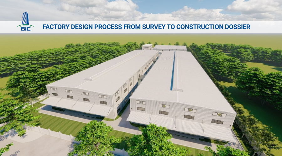
Upon receiving construction design documents, many investors, despite understanding basic symbols, are unsure where to begin reading the drawings to ensure smooth construction and minimize errors. Below is an easy-to-understand and systematic sequence for reading construction drawings that you can refer to:
Step 1: Start with the site plan to understand the relationship between the project's components and the surrounding landscape. For multi-story buildings, you should review the floor plans sequentially from the 1st floor, 2nd floor, and so on, to clearly visualize the spatial arrangement, such as offices, processing zones, canteens, restrooms, and hallways.
Step 2: Next, review the perspective drawings to gain a more visual understanding of the overall shape and space of the factory/building when it is actually constructed.
Step 3: Then, move on to the elevation drawings to visualize the exterior appearance of the project, from the architectural style to the spatial arrangements.
Step 4: Read the section drawings to understand the spatial structure between floors, the height of the factory/building, and the layout within each area.
Step 5: Finally, study the structural drawings to grasp the important technical specifications of the foundation, columns, beams, floors, etc., to ensure the project is solid and meets quality standards.
Following this sequence for reading drawings not only helps investors easily visualize the entire project but also supports better construction supervision, preventing deviations during construction.
The above information is shared by BIC to help homeowners better understand the components of construction design drawings. We hope that with these shares, communication and collaboration with the design unit regarding adjustments before construction will become easier and more effective. This will help minimize unwanted incidents, avoid prolonging the schedule, and prevent unexpected costs. Contact BIC now for professional factory/building design and construction consultation.