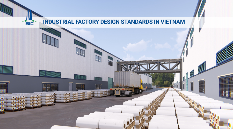
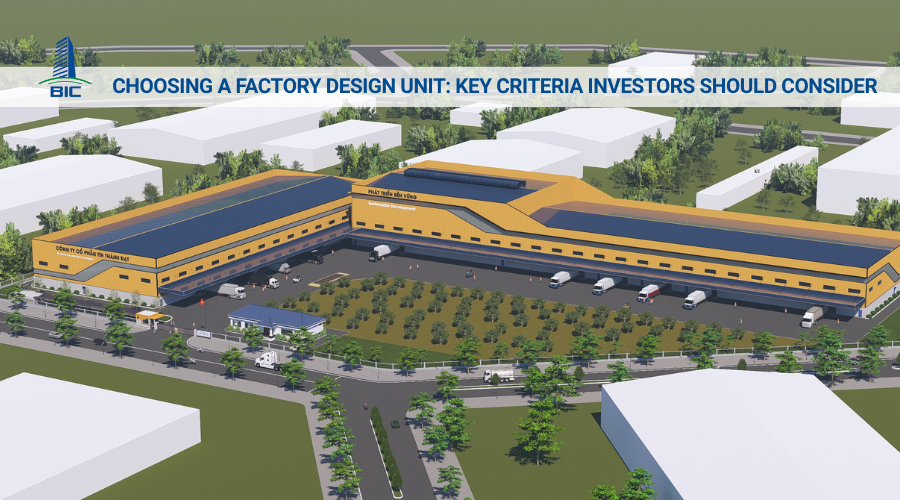
A factory layout is not merely a mechanical enclosure that protects machinery. It is the backbone that shapes operational productivity and the profit margin of a manufacturing business. In reality, up to 40% of time waste and additional operating costs originate from incorrectly arranged material movement flows during the technical documentation stage. Designing a layout based on intuition, without proper industrial ergonomics and technology flow calculations, always leads to overlapping traffic routes, conflicts between forklifts and walking workers, and increased volumes of temporary work-in-process inventory in intermediate zones.
Applying a scientific factory design solution helps investors tailor the space according to actual equipment capacity, free up clear usable area through large-span steel frame systems, and optimize the movement route of raw materials from the input warehouse to the finished goods warehouse. In this article, BIC provides an in-depth analysis of layout zoning principles, compares the advantages and disadvantages of standard production flow models such as U-flow, I-flow, and L-flow, and explains how to synchronize construction design with on-site factory construction methods. These quantitative insights will help business owners proactively control investment capital, optimize technical infrastructure, and build an industrial factory space with the highest economic efficiency.
Production flow management, or internal material flow management, is a core issue in modern industrial architecture. Understanding the nature of these flows helps the design unit arrange space scientifically, prevent waste, and ensure that the production line operates at maximum efficiency.
Internal material flow is the closed and continuous movement route of raw materials and semi-finished goods throughout the process of transformation into finished products:
- Sequential route: The flow begins at the raw material receiving area, or input warehouse, moves through machining, cutting, stamping, or assembly machine clusters, passes through the quality control (QC) area, and ends at the finished goods warehouse, ready for dispatch.
- Objective of construction design: Establish the shortest possible route with no dead time, no material backtracking, and minimal unnecessary loading and unloading frequency by workers.
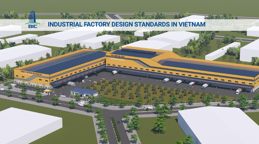
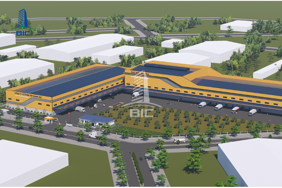
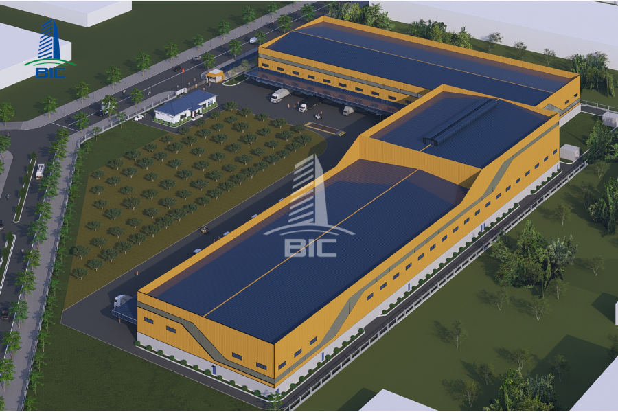
Depending on the land shape, industry characteristics, and production technology, a factory design dossier will apply one of the following three classic flow diagrams:
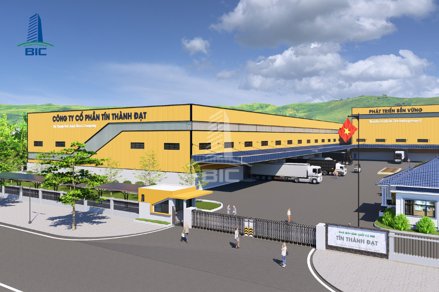
- Straight-line layout, or I-flow: The receiving and dispatch areas are located on opposite sides of the industrial factory. This model is suitable for continuous, highly automated production lines such as electronic component assembly and food processing. Its greatest advantage is the complete elimination of reverse traffic, enabling fast material movement. However, it requires a land plot with significant length.
- U-shaped layout, or U-flow: The raw material receiving door and finished goods dispatch door are located on the same façade of the factory. This is an ideal model for garment manufacturing, precision mechanical processing, or logistics centers. This layout helps optimize labor and loading equipment at the loading dock and makes it easy to expand the factory backward. However, it requires strict control at the U-turn area to avoid congestion.
- L-shaped layout, or L-flow: The material flow turns 90 degrees at an intermediate zone before moving to the finished goods warehouse. The L-flow model is a perfect solution for corner plots, square-shaped plots, or packaging and woodworking industries, where dusty and noisy stages must be completely isolated in a separate branch.
When factory design is disconnected from the technology flow diagram, the business suffers direct daily economic losses:
- Internal traffic conflicts: The drawings do not clearly separate lanes for forklifts and walking paths for workers. As a result, forklift movement speed is significantly reduced to ensure safety, or more seriously, workplace accidents may occur and stop the production line.
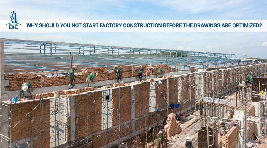
- Work-in-process congestion, or WIP: Due to unreasonable distances between machine clusters, semi-finished products cannot immediately move to the next stage and must wait on the floor. This consumes additional floor area, forces the business to invest in extra storage racks and pallets, and creates opportunity costs because working capital becomes tied up. Any later correction, demolition, or partition wall modification to redesign movement flow after factory construction has been completed will push the initial investment cost much higher.
To translate theoretical drawings into actual operation, the construction design process must strictly follow industrial ergonomics and structural engineering principles, ensuring load-bearing capacity and maximum flexibility for the production space.
The master plan drawing is the concretization of machinery geometry into the construction space. The design and construction consulting unit must collect complete technical data from equipment suppliers:
- Calculating safety distances: Precisely determining the length, width, and height of each machine cluster, the safety corridor for operators, and reserved space for opening machine doors during periodic maintenance and repairs.
- Determining steel frame column spacing: Based on machinery coordinates, engineers calculate the distance between column gridlines, or column spacing, so the steel frame does not interfere with production line positions while also optimizing column distribution density to reduce raw material costs.
The factory floor is the area subjected to the greatest dynamic loads and mechanical abrasion. A design that lacks geotechnical calculations will lead to floor cracking after only a few months of operation:
- Reinforcing the subgrade to technical compaction density: Based on the geotechnical survey report, the soil under the floor must be specified for compaction to at least K95 density to eliminate underground mud pockets and prevent localized settlement.
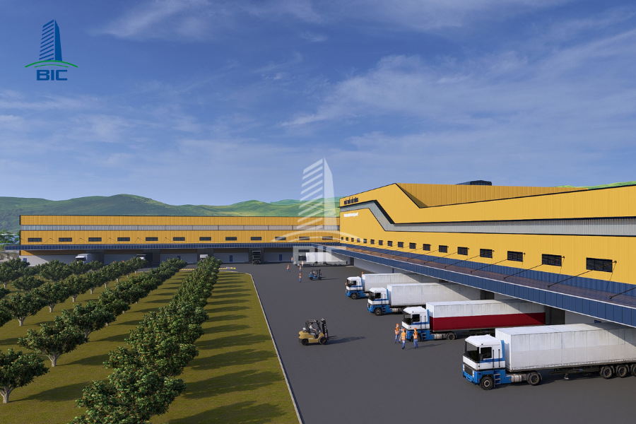
- Synchronizing machine foundation loads and floor thickness: At locations where stamping machines or compressors with strong vibration are placed, the machine foundation must be designed as an isolated block separated from the factory floor by expansion joints. The thickness of the reinforced concrete floor, usually from 150mm to 250mm, and the concrete grade, at least M300, must be calculated to match the compressive load on each forklift wheel. This should be combined with hardener powder or epoxy coating to resist chemicals and prevent dust generation.
Modern industrial architecture prioritizes minimizing internal load-bearing columns to maximize usable area inside the factory:
- Advantages of large-span solutions: Factory design using pre-engineered steel rafter frames allows clear spans from 30m to more than 60m without intermediate column rows. Increased clear usable space allows investors to easily arrange long conveyor systems or change zoning structures when production technology changes.
- Flexibility for future expansion: When the business needs to increase production capacity, pre-engineered steel structures make it easy to extend additional bays or install lightweight mezzanine floors without affecting the structural integrity and load-bearing capacity of the existing factory system.
A highly functional design cannot be separated from the mechanical and electrical network and statutory safety solutions. This synchronization ensures a smoother factory construction process and easier maintenance in the future.
The mechanical and electrical network supplies energy for the entire factory. M&E system design must closely follow the exact coordinates of production equipment:
- Planning power cable routes: Instead of running loose electrical cables across the floor, which creates fire and occupational safety risks, M&E drawings design underground cable trenches with stainless steel covers or solid overhead cable tray systems, dropping vertical cables precisely to the local electrical cabinet of each machine.
- Optimizing technical pipelines: Production water supply pipes, compressed air pipes, and wastewater collection pipes are grouped into technical shafts along factory walls, helping minimize space usage and avoid conflicts with forklift movement routes.
The microclimate inside a factory directly affects worker health and the durability of machine components:
- Applying natural lighting solutions: Construction design dossiers arrange specialized translucent roofing strips with a ratio of 5% to 10% of roof area, combined with glass wall windows to maximize daylight use and reduce lighting electricity costs by up to 30%.
- Negative-pressure ventilation system: A combination of louver systems that bring fresh air in at low wall elevations and automatic roof exhaust fans continuously circulates air, removes hot air, and maintains stable temperatures inside the factory without requiring a costly high-capacity central air-conditioning system.
The biggest mistake that causes many projects to be suspended or unable to enter operation is fire safety design that violates regulations:
- Compliance with current regulations: The factory design unit must strictly apply QCVN 06:2022/BXD to calculate fire compartments, distance to the nearest emergency exit, and the width of roads for fire trucks around the factory.
- Ensuring legal completion acceptance: The design must detail the automatic sprinkler network, smoke detectors, and fireproof coating or wrapping solutions for the main load-bearing structural frame. Accurate integration of these elements helps investors quickly obtain fire protection design approval documents, creating a foundation for smooth completion acceptance and building ownership registration later.
To protect investment capital and fully translate optimized drawing concepts into on-site construction, business owners need to apply modern project management tools.
Building Information Modeling (BIM) is currently one of the most advanced tools for design quality control:
- Integrated 3D simulation: BIM allows architectural, steel structural, and M&E drawings to be merged into a single three-dimensional spatial model. Engineers can visually inspect every factory component before construction begins.
- Early clash detection: The system automatically warns of geometric conflicts, such as ventilation ducts penetrating steel beams or fire protection pipes overlapping with electrical cable trays. Resolving these errors on computers completely eliminates the risk of stopping work for on-site corrections, saving hundreds of millions of VND in wasted labor and materials.
The Bill of Quantities, or BOQ, is the financial control foundation for investors:
- Clearly quantifying specifications: Require the design and construction unit to prepare a BOQ detailing each type of cladding sheet, tonnage of pre-engineered steel frame, concrete grade for load-bearing floors, and electrical equipment codes.
- Preventing additional cost traps: Having an accurate BOQ based on an optimized design helps businesses organize bidding easily and completely eliminate situations where contractors use vague unit prices or intentionally underquote quantities to win low-price bids, then continuously pressure investors to sign additional cost appendices during construction.
The Design & Build model provides comprehensive management advantages for industrial construction projects:
- One single point of responsibility: Investors do not have to coordinate conflicts between a separate drawing preparation unit and an on-site construction contractor. The general contractor takes full responsibility from geotechnical surveys and technical documentation to steel structure erection and load-bearing concrete floor casting.
- Ensuring technical consistency: The general contractor’s site engineers clearly understand every geometric detail and functional intention in the factory design drawings. This consistency helps anchor bolts achieve high positioning accuracy, pre-engineered steel rafter frames fit together properly, and the project reach completion on schedule, meet technical quality standards, and maximize the efficiency of the company’s investment capital.
An optimized factory design for functionality and production flow is the sustainable foundation for the long-term growth of every manufacturing business. Scientifically calculating internal material flows according to standard diagrams such as I-flow, U-flow, or L-flow, combined with large-span pre-engineered steel frame solutions, not only frees up floor area and maximizes the operating efficiency of machinery lines, but also eliminates traffic bottlenecks that cause occupational safety risks.
In addition, synchronizing M&E technical infrastructure from the drawing preparation stage and applying modern management tools such as BIM technology and detailed BOQ quantity takeoff will help investors proactively control budgets, protect capital, and completely prevent the risk of demolition and on-site rework. To bring the project to completion safely, meet technical standards, and optimize economic efficiency, business owners should prioritize cooperating with reputable general contractors with full-package design and construction capability and deep practical experience, thereby obtaining a sustainable industrial factory that delivers the highest business operation efficiency. Contact BIC for detailed consultation.