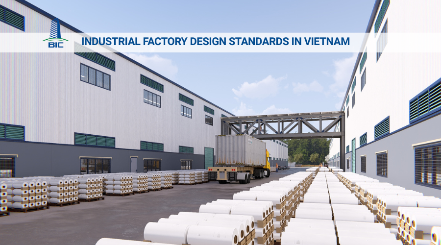
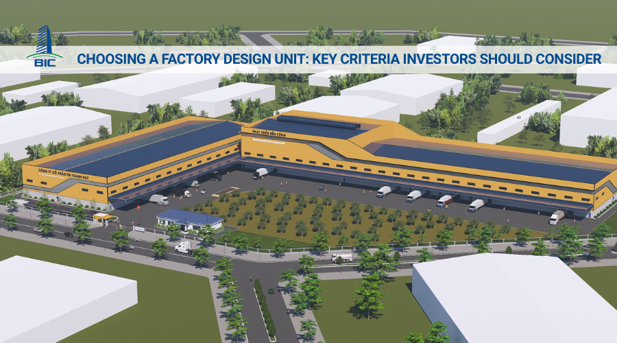
Investing in the construction of an industrial factory requires substantial capital and thorough preparation in both technical and legal aspects. To ensure the project achieves high production efficiency, investors must closely control the entire lifecycle of the facility, from geotechnical surveys and technical drawing preparation to on-site erection and completion acceptance. In practice, a lack of synchronization in the construction design stage or errors during factory construction directly leads to risks such as material waste, schedule delays, and failure to meet fire prevention and fighting approval requirements for factory operation.
In this article, BIC provides a detailed roadmap for the factory design and complete construction process from A to Z according to current technical standards. By clarifying quality control points in each design and construction stage, investors will have sufficient data to assess contractor capability, proactively manage cash flow, and ensure that the facility operates stably and safely.
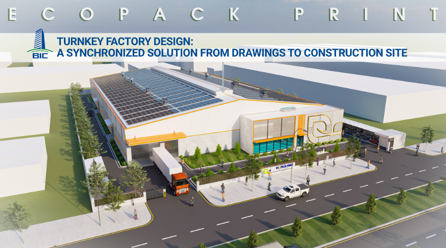
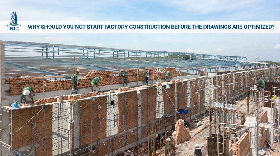
In industrial construction, managing the design and construction stages separately often creates a large gap between drawing theory and actual implementation. Applying a synchronized management mechanism from the beginning is an essential solution to optimize resources, control technical quality, and protect the investor’s capital.
The lack of connection between design engineers and site engineers is a common cause of dimensional deviations, conflicts between M&E systems and load-bearing structures, or drawings that are not compatible with actual construction machinery capabilities.
When these two departments coordinate from the planning stage, design engineers can adjust drawings based on actual site survey data and the contractor’s practical construction methods. This interaction helps completely eliminate technical errors on paper before the project begins implementation. Every detail in the factory design dossier, from column spacing and ceiling height to floor load-bearing positions, is aligned with actual conditions, ensuring absolute feasibility when entering the factory construction stage.
Under the traditional method, investors must complete the entire design dossier, approve the cost estimate, then select a contractor and begin construction. This sequential process extends the preparation period and delays the time when the factory can be put into operation.
Synchronized management allows investors to apply a fast-tracking construction method to shorten the schedule by 20% to 30%. Specifically:
- As soon as the foundation technical drawings are approved, the site team begins pile driving, foundation concrete casting, and underground infrastructure work.
- During that time, based on detailed component drawings, the mechanical factory simultaneously fabricates the pre-engineered steel frame system, including columns, rafters, and purlins.
- When the foundation concrete reaches the required curing age and passes acceptance, the steel frame is also transported to the site for immediate erection, eliminating waiting time between work packages.
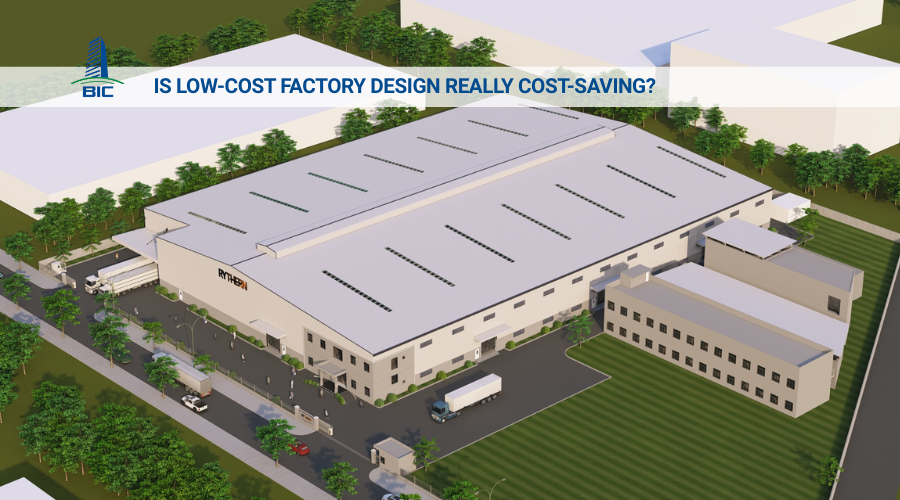
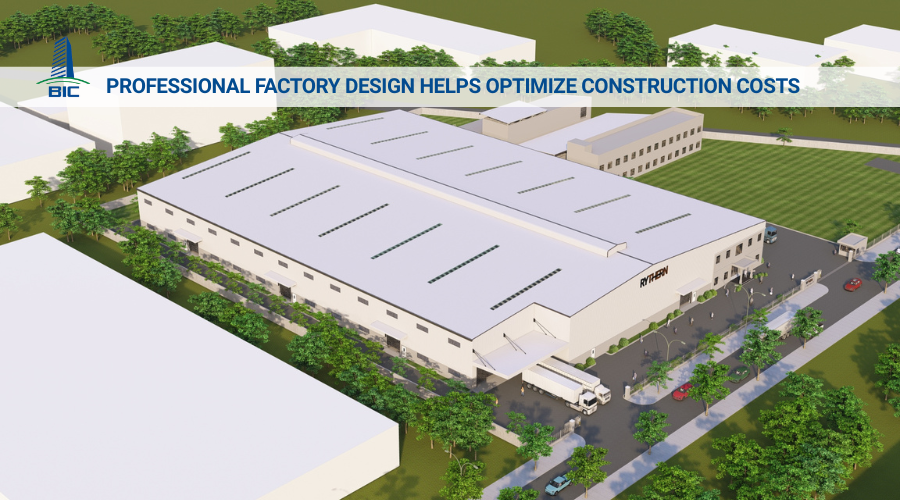
The greatest risk in industrial projects is cost overrun due to inaccurate quantity takeoff or materials that are incompatible with implementation methods.
A closed design and construction process allows engineers to issue an accurate and transparent Bill of Quantities (BOQ) right from the construction design stage. Categories such as steel grades, concrete grades, fire protection pipe standards, and electrical equipment are clearly identified in terms of quantity, technical specifications, and origin. Strict BOQ management from the beginning helps investors lock in the budget, proactively source raw materials, and completely prevent uncontrolled additional costs throughout the construction process.
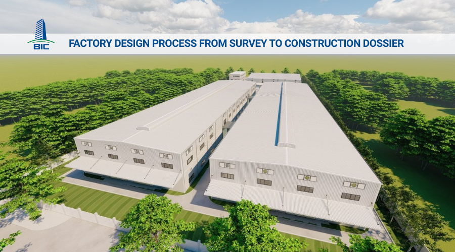
The investment preparation stage lays the technical foundation for the entire project. Any errors or missing data at this stage will directly affect the feasibility and structural safety of the facility later.
The first step in the factory design process is to collect and analyze operational data from the investor. Required information includes:
- Industry and production technology line: Determining whether the factory belongs to heavy industry, mechanical engineering, garment manufacturing, food processing, or electronics in order to apply the corresponding environmental and safety design standards.
- Machinery and equipment loads: Determining the weight, installation location, dimensions, and vibration level of the machinery system planned for installation in order to calculate the thickness and reinforcement structure of the factory floor.
- Expansion plan: Identifying the company’s future needs for capacity upgrades or area expansion in order to arrange appropriate reserved structural solutions on the site layout.
Site survey work provides accurate surveying and geotechnical data so structural engineers can select a suitable foundation solution and prevent settlement or cracking risks under heavy loads.
- Geotechnical drilling: Soil sampling is carried out at critical locations with drilling density and depth in accordance with construction standards. Laboratory test results determine the bearing capacity of the soil, groundwater level, and thickness of weak soil layers.
- Topographic measurement: Accurately identifying the coordinate boundaries of the land plot and the natural elevation of the site to calculate excavation and filling volumes, ensuring that the finished ground level will not be flooded during the rainy season.
The master plan drawing defines the entire spatial structure of the project on the available land area, ensuring optimized usable area and compliance with the construction density regulations of the industrial park.
- Functional zoning: Arranging the main production factory to connect conveniently with the raw material warehouse and finished goods warehouse. The administration office, canteen, and parking area are separated to ensure occupational hygiene and safety while reducing noise.
- Technical infrastructure planning: Positioning the transformer station, wastewater treatment plant, underground water tank, and fire pump station in independent locations that satisfy fire separation safety distances.
- Internal traffic organization: Designing independent routes for container trucks loading and unloading goods, avoiding overlap with workers’ walkways. At the same time, traffic corridors around the factory must meet the minimum width required for fire trucks to access all corners of the facility.
After the master plan is approved, the consulting unit turns design concepts into precise technical specifications. The construction drawing dossier is the highest legal and technical basis for accepting the contractor’s work quality.
The main objective of factory architectural design is to optimize enclosure function, thermal insulation, sound insulation, and create a well-ventilated working environment for employees.
- Wall enclosure solutions: Depending on the requirements of the manufacturing industry, the design may use 100mm to 200mm thick brick walls combined with roll-formed corrugated wall cladding, or insulated panel systems such as EPS, PU, and Rockwool. Panels are especially suitable for factories with high temperature-control requirements such as electronics factories, pharmaceutical facilities, and cold storage warehouses.
- Heat-resistant roofing solutions: The roof may be designed using single-layer cool metal sheets combined with insulation bags, or three-layer metal roofing with a PU insulation layer from 20mm to 50mm thick. The roof slope is calculated at 10% to 15% to ensure rapid rainwater drainage and prevent water stagnation that could cause metal sheet corrosion.
- Natural ventilation and lighting: Skylights are arranged along the roof ridge to release hot air rising from the floor. Louvers installed near the wall base create continuous convection airflow. Translucent roofing sheets are distributed evenly across the roof to make use of daylight, reducing power consumption from electric lighting systems.
The main load-bearing frame structure of the factory usually uses a pre-engineered steel system due to its high load-bearing capacity, flexible span capability, and fast erection time. The structural design process strictly follows Vietnamese standards such as TCVN 5575:2012 on steel structures and TCVN 2737 on loads and actions.
- Component section calculation: Structural engineers use specialized software to simulate and determine the optimal sections of columns, rafters, floor beams, and C-shaped or Z-shaped purlins. This optimization reduces steel weight per square meter of floor area while still ensuring the load-bearing safety factor.
- Stability bracing system design: Roof bracing, column bracing, and purlin bracing systems are arranged using cables or angle steel. The bracing system connects individual steel frames into a rigid spatial structure, resisting horizontal forces from storms or vibration forces when overhead cranes operate.
- Connection details: The drawings detail factory welds and on-site bolted connection systems, including foundation anchor bolts and high-strength bolts used to connect columns and rafters.
The mechanical and electrical system supplies energy and maintains technical conditions for production machinery to operate stably.
- Power supply system: Total power consumption of the machinery line is calculated to design an appropriate transformer station capacity. The drawings clearly indicate underground cable routes, installation locations of the Main Switchboard (MSB), branch distribution boards at each workshop, and suspended cable tray systems. Factory lighting design follows suitable lux illuminance standards for each production stage.
- Water supply and drainage system: The rainwater drainage system is separated from the domestic wastewater and industrial wastewater collection systems. The internal wastewater treatment station is designed with a capacity suitable for the factory’s daily discharge volume.
- Ventilation and air-conditioning system: HVAC: For factories that generate significant heat, such as mechanical and garment factories, the design applies a negative-pressure cooling ventilation system using cooling pads and industrial exhaust fans. For electronics clean rooms or pharmaceutical facilities, the design uses an AHU system combined with specialized dust filtration to control cleanliness, temperature, and humidity.
Based on the completed construction drawing dossier, engineers prepare the Bill of Quantities (BOQ). The BOQ lists in detail:
- Foundation concrete volume, formwork area, and foundation reinforcement weight.
- Total weight of the pre-engineered steel structure in tons.
- Roof sheet, wall sheet, and insulated panel areas in square meters.
- Detailed quantities and technical specifications of electrical equipment, water pipelines, and fire protection equipment.
Based on this quantity table, investors can apply current material unit prices to obtain an accurate total cost estimate for the facility. This serves as the basis for signing a factory construction contract without worrying about unreasonable additional cost risks.
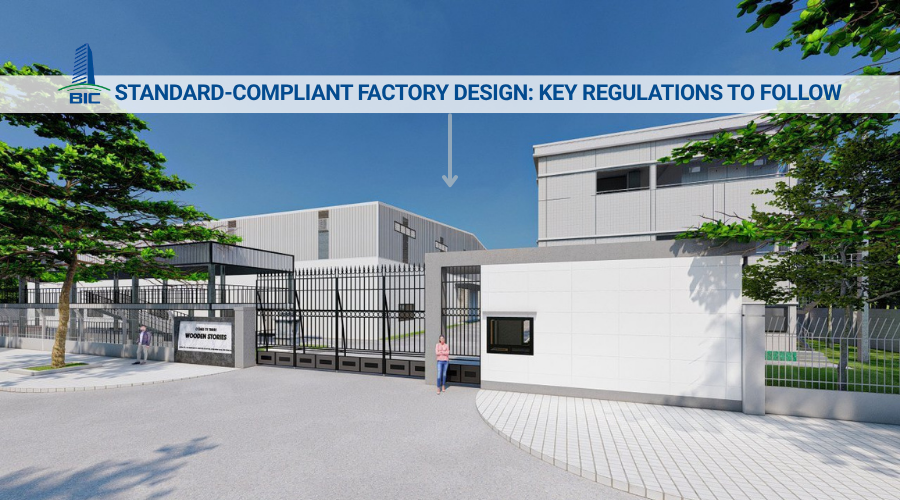
Before on-site construction begins, the project must be legally approved by state management authorities to ensure fire and explosion safety as well as urban planning compliance.
This is a mandatory step and a decisive factor for later project completion acceptance. The fire protection design dossier must strictly comply with QCVN 06:2022/BXD and TCVN 3890:2023.
- Fire-safe architectural solutions: The design must ensure fire separation distances between buildings on the site. It must fully arrange escape routes, emergency exits, and roads around the factory for fire truck operation.
- Fire protection technical systems: The design details the automatic sprinkler network, wall-mounted fire hydrants, automatic fire alarm system using smoke or heat detectors, emergency smoke extraction system, Exit signs, and emergency lighting.
- Structural protection: The drawings clearly specify fireproof mortar wrapping, specialized gypsum board wrapping, or fireproof coating solutions for steel columns and rafters to achieve minimum fire-resistance ratings from R30, R60 to R90 according to the factory scale classification.
The investor or authorized general contractor submits the construction permit application to the Department of Construction or the Management Board of the industrial park in the relevant province or centrally governed city. The application dossier includes:
- Land Use Rights Certificate or industrial park land lease contract.
- Basic design drawings appraised by the construction authority.
- Approval document for the Environmental Impact Assessment (EIA) report or confirmation of environmental protection plan registration.
- Fire prevention and fighting design approval certificate issued by the Fire Prevention and Fighting and Rescue Police Department or Division.
The competent authority will appraise the legality of the dossier and its conformity with the overall planning of the industrial park before issuing the official construction permit, allowing the project to enter the on-site factory construction stage.
This is the stage where technical specifications on drawings are transformed into a real facility. It combines precision mechanical manufacturing at the factory with basic construction activities on-site.
The pre-engineered steel frame is manufactured in a closed process at the mechanical workshop under strict quality control before being transported to the site for erection. The fabrication process includes the following steps:
- Steel cutting and shaping: Specialized CNC cutting machines, either Plasma or Laser, are used to cut raw steel plates into flanges and webs for steel columns and rafters according to the exact dimensions specified in the factory design drawings.
- Assembly and automatic welding: After cutting, the steel plates are placed into an assembly machine to form I-shaped or H-shaped components, then automatically welded using submerged arc welding technology to ensure weld penetration and load-bearing capacity.
- Straightening and welding of auxiliary details: Hydraulic straightening machines are used to correct thermal deformation caused by welding. Workers then weld auxiliary details such as base plates, stiffeners, and purlin cleats.
- Surface cleaning and coating: All steel components are placed in a shot-blasting chamber to achieve Sa 2.5 standard, removing rust and creating surface roughness. The steel is then coated with an anti-rust primer, finishing paint layer, and fireproof coating according to the required technical thickness.
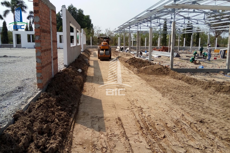
In parallel with steel fabrication, rough construction activities are carried out on-site to create the load-bearing base for the entire factory.
- Earthwork and ground reinforcement: The contractor removes the organic soil layer and excavates foundation pits to the design elevation. In weak soil conditions, reinforced concrete piles or spun piles are driven to reinforce load-bearing capacity.
- Foundation and grade beam concrete casting: Foundation reinforcement and formwork systems are installed before ready-mixed concrete is poured for isolated footings, strip foundations, or raft foundations combined with grade beams to tie the foundation heads together.
- Anchor bolt positioning and installation: This is an especially important technical step. High-strength anchor bolts used to connect steel column bases to concrete foundations are positioned accurately using a theodolite or total station. The positional tolerance of the anchor bolt group must be within the allowable limit of less than 2mm to ensure the frame is not eccentric during erection.
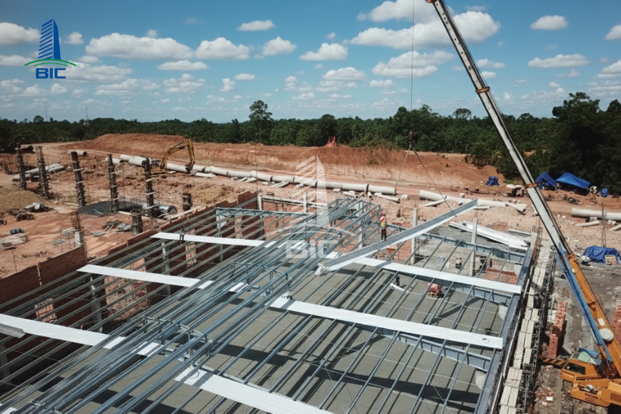
When the foundation concrete reaches the required load-bearing age and the steel frame is transported to the site, the body structure erection is carried out using heavy-duty mechanical equipment.
- Erection of the braced bay: One factory bay, usually the bay with column bracing and roof bracing, is selected for erection first. The columns, rafters, purlins, and bracing cables of this bay are tightened with high-strength bolts to form a rigid box structure, serving as the support point for the erection of subsequent bays.
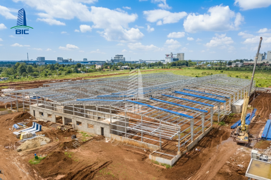
- Erection of the entire main frame: The following rafter frames are erected sequentially from the inside outward. The contractor uses specialized cranes with suitable lifting capacities, from 25 tons to 50 tons depending on component size, together with high-altitude workers to connect rafter sections at height.
- Bolt tightening inspection: All bolts connecting the main load-bearing structure must be tightened with hydraulic wrenches or torque wrenches with gauges, ensuring the specified technical torque in the construction design dossier is achieved.
This work package isolates the interior factory space from the external weather environment and prepares a clean site for M&E and flooring works.
- Metal roofing and wall cladding installation: Roof sheets, wall sheets, or envelope panels are pulled into place and fixed with screws. Roofing work must comply with correct wave overlap techniques and include the installation of gutters, rainwater downpipes, and storm-proof clips to prevent water leakage or roof uplift during strong winds.
- Perimeter wall construction and door finishing: Brick walls are constructed around the base of the factory, commonly ranging from 1.2m to 2.5m in height, to increase protection, resist impact, and prevent water intrusion from outside. Heavy-duty roller shutters for truck access, fire-rated emergency exit doors, and glass window systems for natural lighting are installed.
The factory floor is directly affected every day by production activities, forklifts, and machinery. Therefore, the pouring and floor finishing process requires extremely strict control.
- Subgrade preparation: The soil base is recompacted with heavy rollers to achieve K95 compaction. A 10cm to 20cm thick crushed stone bedding layer is spread and compacted flat. A waterproof sheet or plastic membrane is laid to prevent concrete water from seeping into the ground and to stop rising damp from the soil from reaching the floor surface later.
- Floor reinforcement installation: Welded wire mesh or two-layer reinforcement is installed according to the load-bearing diagram in the design and construction drawings. Concrete spacers are arranged to ensure the correct thickness of the concrete cover for reinforcement. Expansion joints and dowel bars are installed at boundary locations to prevent floor cracking caused by thermal deformation.
- Concrete pouring and surface finishing: High-grade ready-mixed concrete, usually from grade 250 to grade 350, is poured with slump and thickness continuously controlled. Plate compactors and internal vibrators are used to compact the concrete. When the concrete begins to set, specialized power trowels are used together with hardener powder to strengthen the surface against abrasion, or the surface is ground flat to prepare for epoxy coating that prevents dust accumulation and resists chemicals.
After the building envelope and floor are completed, the project enters the stage of installing auxiliary technical infrastructure systems. This stage determines the actual operational capacity of the factory production line.
The mechanical and electrical system is implemented based on the machinery positioning layout defined in the design and construction dossier. The implementation items include:
- Cable tray system installation: Supports and suspended cable tray systems are positioned and fixed on the steel rafter frame. Cable tray routes must be straight, enclosed at right-angle corners, and maintain safe distances from water pipeline systems.
- Power cable pulling and electrical panel installation: Power cables are pulled from the transformer station to the Main Switchboard (MSB), then connected to Distribution Boards (DB) at each workshop. Cable lugs must be firmly crimped with hydraulic crimping tools and clearly labeled for maintenance.
- Lighting and grounding system arrangement: Specialized high-bay lights for factories are installed with density and mounting height that meet illuminance standards. At the same time, grounding rod fields are installed for the production electrical system and roof lightning protection system, ensuring grounding resistance is below the level required by industry standards.
The fire protection system is fully installed to prepare for acceptance inspection by competent authorities.
- Pipeline network and sprinkler head installation: Fire water supply pipe mains made of black steel or galvanized steel are installed along the rafter frame. Automatic sprinkler heads are installed according to the designed spacing. Alarm valve assemblies are installed to control pipeline pressure.
- Fire alarm control panel and pump assembly installation: Smoke detectors and heat detectors in production and office areas are connected to the central fire protection control panel. In the technical area, the fire pump assembly is installed, including the main electric pump, backup diesel pump, and jockey pump, directly connected to the water source from the underground tank.
- Construction of external infrastructure works: Completing the rainwater drainage channel system around the factory, asphalt paving or concrete casting for internal roads, construction of security fences and guard houses, and completion of internal traffic lighting systems.
The final stage of the process aims to evaluate the overall quality of the facility and complete legal procedures so the factory can officially begin operation.
Before handover, the general contractor coordinates with the supervision consulting unit to conduct individual and integrated test runs for all technical systems.
- Pipeline pressure testing: Water is pumped into the entire production water supply pipeline system and fire protection pipeline system, and the systems are held under pressure for the required period to check the tightness of welds and threaded joints.
- Integrated fire protection system testing: A simulated fire incident is conducted to check the sensitivity of smoke detectors, signal transmission to the central control panel, activation of alarm bells and lights, emergency smoke extraction system, and automatic operation of the fire pump station.
- Environmental parameter measurement: Lighting intensity, ventilation airflow speed, and operating noise levels of auxiliary machinery are checked to ensure compliance with occupational hygiene standards.
The facility is only eligible for operation when written approval is issued by specialized management authorities.
- Fire protection acceptance: The Fire Prevention and Fighting and Rescue Police Department or Division conducts an on-site inspection, compares the installation with the previously approved drawings, and performs system activation tests. If requirements are met, the competent authority issues a written approval of fire prevention and fighting acceptance results.
- Project completion acceptance: The investor submits the completion dossier, including as-built drawings, quality certificates for input materials, concrete sample compression test results, and weld ultrasonic testing results, to the Department of Construction or the industrial park management board for inspection and issuance of the project completion certificate.
After all legal documents are obtained, the general contractor hands over the asset to the investor.
- Document handover: The general contractor transfers the full as-built dossier, equipment catalogs, operating procedures, and maintenance instructions for M&E and fire protection systems to the investor’s factory management team.
- Warranty clause activation: The warranty period is calculated from the date the handover minutes for putting the facility into use are signed. Typically, the steel structural frame is warranted for 24 to 60 months, architectural finishing works for 24 months, and M&E and fire protection equipment for 12 months in accordance with the commitments in the design and construction contract.
The process of factory design and complete construction for industrial facilities is a sequence of closely connected and orderly technical work packages. A detailed understanding of each stage, from the initial geotechnical survey to the fabrication process and completion of mandatory legal procedures, helps investors proactively supervise quality, optimize progress, and control investment capital most effectively.
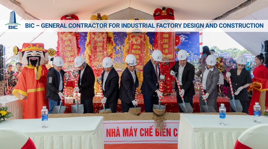
To ensure that the project meets current quality standards and operates stably over the long term, investors should prioritize cooperation with general contractors that hold appropriate construction activity capacity certificates, own independent steel fabrication factories, and have practical experience in similar projects. Careful preparation from the construction design stage is the optimal solution for realizing a safe, productive, and sustainable production space for the business. Contact BIC for consultation on the optimal solution for your industrial factory project.