In mechanical factories, steel structure manufacturing plants, industrial equipment factories, and building material facilities, overhead cranes are used to lift and move heavy loads. This equipment directly affects the columns, corbels, crane runway beams, bracing system, and building foundations. Therefore, designing a factory with an overhead crane requires a more detailed calculation process than a standard industrial factory.
Right from the construction design stage, investors need to clearly define the lifting capacity, crane span, hook lifting height, runway length, and operating frequency. These parameters form the basis for selecting the factory height, arranging column spacing, calculating load-bearing structures, and coordinating the electrical system, fire protection system, and other technical work items.
If crane-related information is provided late or inaccurately, the building may require structural reinforcement, crane rail elevation adjustment, equipment replacement, and an extended factory construction schedule. In this article, BIC analyzes the key issues investors should consider when designing and constructing a factory with an overhead crane, from determining operational requirements to controlling structure, safety, and future expansion capacity.
An overhead crane does not only generate vertical loads. It also creates longitudinal forces, lateral forces, and vibration during operation. These forces are transferred from the crane wheels to the rails, crane runway beams, corbels, main columns, and foundations. Therefore, when designing a factory with an overhead crane, engineers must calculate both static and dynamic loads instead of relying only on the rated lifting capacity of the equipment.
Static loads include the self-weight of the crane bridge, main girder, end carriages, trolley, hoist, and related components. These loads act continuously on the rail system and supporting structure, even when the crane is not lifting any load.
Dynamic loads occur when the crane lifts, lowers, accelerates, decelerates, or stops. In addition to the weight of the lifted object, the structure must also withstand acceleration effects, vibration, and braking forces. For equipment with lifting capacities from 5 tons to 30 tons or more, the load transferred to each wheel can vary significantly depending on the position of the trolley and lifted load.
When the trolley moves along the crane girder, the load becomes more concentrated on the wheels closer to the lifting point. Starting or braking creates forces along the runway direction. Rail misalignment, uneven movement between the two crane ends, or pulling loads in an incorrect direction can also generate lateral forces. These forces directly affect the runway beams, corbels, bracing system, and overall stability of the factory frame.

If dynamic loads are not correctly determined, runway beams may deflect, vibrate, or deform beyond allowable limits. Differences in elevation or spacing between the two crane rails make wheel movement unstable, increase friction, accelerate equipment wear, and create additional lateral forces on the structure.
Long-term repeated loading also increases the risk of metal fatigue at stress concentration points such as welds, connection plates, corbels, and runway beam connections. Common signs include cracked welds, corbel deformation, twisting of steel columns, rail misalignment, and frame vibration during crane operation.
In cases where the crane brakes suddenly or operates with heavy loads, lateral forces may deform the bracing system and affect the overall stability of the industrial factory. The risk becomes higher when the building has a large span, tall columns, continuous crane operation, or differential foundation settlement.
Therefore, the construction design dossier must use complete technical data provided by the overhead crane manufacturer, especially maximum wheel load, wheel spacing, duty class, travel speed, and braking force. Accurate calculation from the beginning helps ensure structural safety, reduce operational damage, and limit reinforcement costs after factory construction.
Determining crane parameters from the beginning helps the design unit select the correct structural solution, building height, and operating space. If the equipment is added after the design dossier has already been completed, many work items may need to be adjusted, increasing costs and affecting the project schedule.
An overhead crane creates vertical loads from the self-weight of the equipment and lifted objects, while also generating lateral forces, braking forces, and dynamic loads during operation. These forces are transferred through the wheels to the rails, runway beams, corbels, steel frame, bracing system, and foundations. Unlike static loads, loads during crane operation continuously change according to trolley position, lifted load weight, and acceleration or deceleration status. Therefore, factory design must be based on specific technical data of the equipment.
The height of a factory with an overhead crane must be determined based on hook lifting height, rail elevation, crane girder size, and the safety clearance above the equipment. These parameters directly affect the eave height, roof ridge height, and the ability to arrange bracing systems, pipelines, cable trays, and fire protection equipment. Inaccurate calculation can reduce the actual lifting height or cause conflicts with technical systems.
Calculating crane requirements during the design stage helps avoid later reinforcement of columns, foundations, or runway beams after construction has already started. Investors can also avoid having to replace equipment due to insufficient span or height. As a result, factory construction can be better controlled in terms of cost, schedule, and safety.
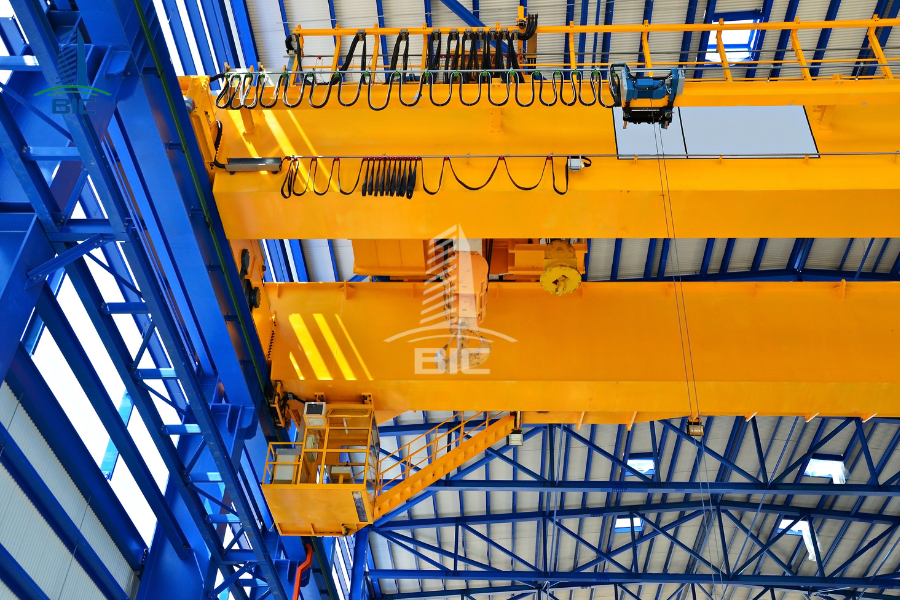
Before factory design begins, investors should coordinate crane operating parameters with the equipment supplier and design consultant. These parameters provide the basis for determining layout, building height, load-bearing structure, and suitable electrical systems.
The lifting capacity should be determined based on the heaviest load under actual production conditions, including lifting accessories when necessary. Investors should not rely only on the average weight of products. Machinery relocation, equipment maintenance, and future production expansion should also be considered to avoid selecting a crane that is too small or excessively oversized.
The crane span is the working distance between the two crane rails and is directly related to the factory span and column row positions. The runway length should closely follow the production area that the crane must serve. Correctly determining the operating range helps reduce unnecessary rail, runway beam, and power supply quantities.
Hook lifting height is determined based on machinery dimensions, lifted load height, and material handling procedures. This parameter is different from the overall factory height. During calculation, the distance from the finished floor to the highest hook position must be checked, while sufficient space must also be reserved for the hoist, crane girder, and upper safety clearance.
The number of lifting cycles per shift, daily operating time, and percentage of operation under heavy loads affect the crane duty class. Cranes operating continuously require motors, brakes, wheels, and supporting structures with better resistance to repeated loads than equipment used only for short periods.
Investors need to define hoisting speed, trolley travel speed, and full crane travel speed. Control methods may include pendant control, cabin control, or remote control. For assembly lines requiring high precision, suitable speeds should be selected, and inverter control systems should be considered.
Temperature, humidity, dust, chemicals, and corrosive agents directly affect materials, protective coatings, motors, and electrical systems. In areas with fire or explosion risks, overhead cranes must use electrical equipment suitable for the safety requirements of the production environment.

Overhead cranes operate in the same space as the structure, electrical systems, pipelines, and fire protection equipment. Therefore, these work items must be coordinated during the factory design stage to ensure operating clearance, maintenance access, and safe use.
The positions of rails, runway beams, and corbels must match the column system, rafters, roof bracing, and main connections. The clearance above the crane must be checked to avoid collision with rafters or bracing systems. Loading and unloading doors should be located within a convenient lifting range. For areas with open vertical space or tall machinery, the design unit should simulate the movement path of lifted objects to avoid conflicts.
The power supply for the crane must meet the capacity requirements of the hoisting motor, trolley motor, and travel mechanism. Along the runway, conductor bars or flexible cables may be arranged depending on equipment type and working environment. The electrical cabinet should include protection against overload, short circuit, and phase loss. Grounding, leakage protection, and emergency stop buttons must be calculated and integrated. Backup power is only necessary in special cases related to production safety.
Air ducts, process pipelines, cable trays, and fire protection pipes must not be located within the movement range of the crane and lifted loads. The elevations of sprinkler heads, fire alarm devices, and smoke extraction systems must also be checked to avoid collision while still ensuring the required protection coverage according to the design.
A BIM model helps display the overhead crane, structure, and MEP systems in the same space. The design unit can simulate movement ranges, check elevations, and detect clashes before construction. The coordination results provide a basis for more accurate construction drawings, minimizing adjustment, dismantling, and rework on-site.

Before starting the design of a factory with an overhead crane, investors need to provide the production process diagram, material movement direction, and lifting range in each area. The machinery list, equipment dimensions, proposed installation positions, and maintenance requirements should also be defined relatively clearly. These data help the design unit arrange the layout, column spacing, and crane runway to suit production activities.
For the overhead crane, important information includes the maximum load to be lifted, lifted object dimensions, hook lifting height, span, runway length, and operating frequency. Investors should work early with the equipment supplier to obtain data on crane dimensions, wheel loads, electrical capacity, and installation requirements. Providing only the rated lifting capacity is not sufficient for structural calculation.
In addition to current needs, businesses should identify the possibility of future load increases, production line expansion, or runway extension. Temperature, humidity, dust, chemicals, and fire or explosion risks must also be fully communicated. Finally, the expected schedule and budget will help the consultant select a suitable solution. The more accurate the input data, the closer the factory design will be to actual needs, limiting excessive safety allowances and reducing additional costs during construction.
Designing a factory with an overhead crane requires synchronization between production technology, equipment parameters, and building structure. Factors such as lifting capacity, wheel loads, span, lifting height, operating frequency, and runway range must be determined before construction design begins. These are the basis for accurately calculating foundations, columns, corbels, runway beams, bracing systems, and factory height.
Investors should also coordinate early with the crane supplier and design unit to control conflicts between lifting equipment and the structure, electrical system, MEP systems, and fire protection system. Preparing complete data from the beginning helps limit structural reinforcement, equipment changes, and rework during factory construction.
With experience in industrial factory design and construction, BIC can support investors in developing solutions that match production needs, operating conditions, and expansion plans. A synchronized design and construction solution helps businesses control costs, maintain schedules, and ensure safety throughout the building’s service life.