In mechanical factories, steel structure manufacturing facilities, industrial equipment plants, and building material factories, overhead cranes are used to lift and move machinery, molds, and heavy goods. This equipment not only affects the production line, but also directly impacts the columns, column corbels, crane runway beams, bracing systems, and foundations of the building.
Factory design with overhead cranes therefore requires more careful calculation than standard factory design. Lifting capacity, crane span, hook lifting height, runway length, and operating frequency are data that must be determined from the beginning. If an overhead crane is added after the building has been completed, the investor may have to reinforce the structure, modify the electrical system, or adjust the production layout.
In the article below, BIC analyzes structural requirements, technical systems, the construction design process, and criteria for choosing a suitable general construction contractor for factories with overhead cranes.
An overhead crane is equipment used to lift and move machinery, molds, raw materials, or goods within the factory space. A typical system includes the crane bridge, end carriage, hoist, motor, wheels, rails, and control unit. The load of the goods must be distinguished from the self-weight of the equipment. During operation, forces are transferred from the wheels to the rails, crane runway beams, column corbels, columns, and building foundations.
Single-girder overhead cranes are suitable for moderate loads and spans. Double-girder overhead cranes are commonly used when lifting loads are large or operating frequency is high. Suspension cranes and monorail cranes are suitable for production lines with specific movement ranges. Selection must be based on load capacity, span, runway length, and operating mode.
A factory should be equipped with an overhead crane when it frequently handles molds, steel coils, structural components, machinery, or heavy goods. This equipment helps reduce dependence on forklifts and shorten transportation time, but investors also need to consider investment cost, electricity consumption, maintenance, and safety requirements.
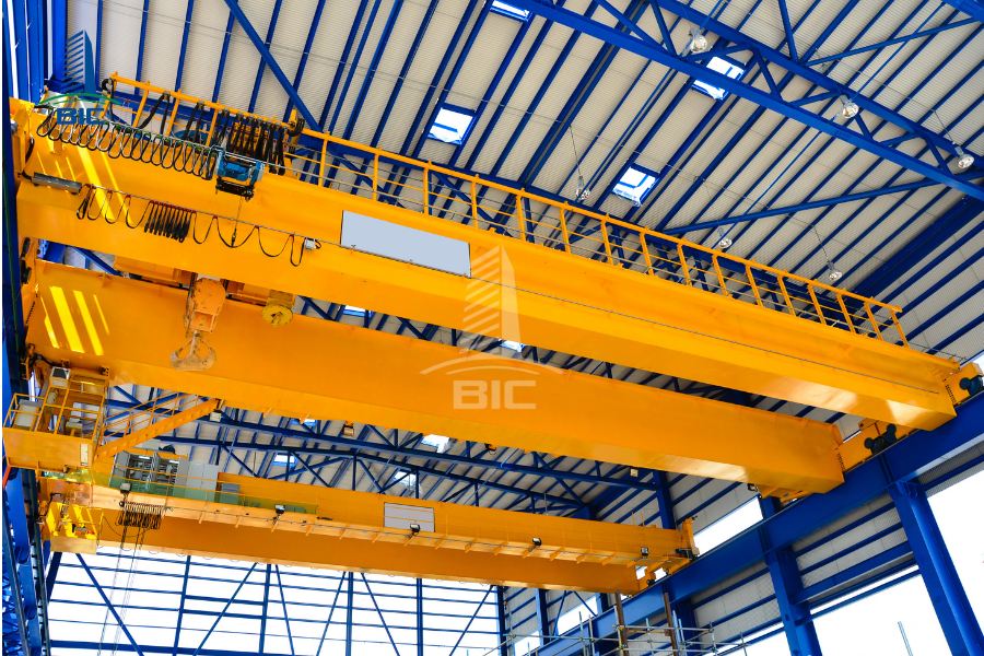
An overhead crane is not merely equipment installed inside a factory. It creates a dedicated load system acting on the entire building. Therefore, crane specifications must be determined before calculating frames, runway beams, columns, and foundations.
Static loads include the weight of the crane bridge, main girder, end carriage, hoist, and lifted goods. When the equipment accelerates, decelerates, lifts, lowers, or stops suddenly, the structure also receives horizontal forces, braking forces, and vibration. These repeated effects influence crane runway beams, column corbels, bracing systems, and connections, so calculations cannot be based only on the weight of the goods.
The building height must satisfy rail elevation, hook lifting height, crane dimensions, and safe clearance from the roof. At the same time, the design must avoid conflicts between the crane and bracing systems, lights, fans, pipelines, cable trays, and fire prevention and fighting systems.
The runway location must suit the movement flow of raw materials, machinery, and finished goods. The factory also needs access space for inspecting rails, motors, hoists, and control cabinets. Calculating these requirements from the beginning helps limit later structural reinforcement, equipment changes, and production interruptions.
The more complete the input data are, the closer the factory design dossier with overhead cranes will be to actual operational needs, while reducing adjustments during construction. Investors should not only provide nominal lifting capacity, but should fully describe the equipment, goods, production line, and site conditions.
The maximum load, size of lifted objects, hook height, lifting speed, travel speed, and working frequency need to be determined. Crane self-weight, wheel loads, electrical capacity, and operating mode are also the basis for calculating runway beams, columns, foundations, and power supply systems.
The dossier needs to show crane span, runway length, rail elevation, column spacing, end positions of the runway, and safety clearance. These specifications directly affect factory height, frame dimensions, roof position, and the arrangement of pipelines and cable trays.
Investors need to provide the process diagram, material movement direction, lifting positions, machinery list, and maintenance requirements. The dimensions, weight, output, and frequency of goods receiving and dispatch help the design unit arrange the crane runway in line with logistics.
Geotechnical conditions, elevations, groundwater level, traffic, power supply, and production environment all affect the construction design solution. If the investor plans to increase loads, expand the production line, or extend the runway, connection points and structural capacity need to be reserved from the beginning.
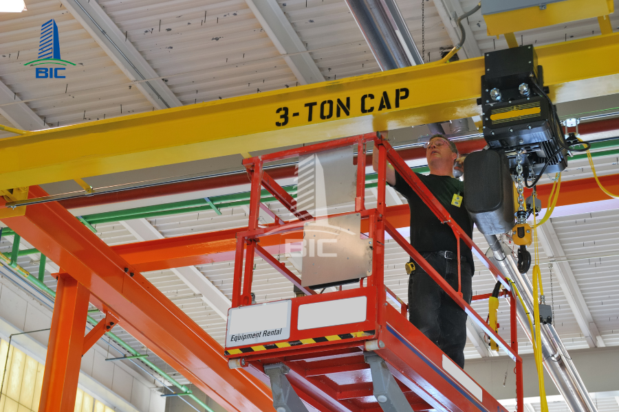
The structure of a factory with overhead cranes must be calculated according to the full load path from the equipment down to the ground. Loads do not stop at the crane wheels, but continue through the rails, runway beams, column corbels, columns, bracing systems, and foundations. Therefore, selecting a steel frame based only on factory span or nominal lifting capacity is not enough to ensure safety and operational efficiency.
Design loads must include the weight of the crane bridge, main girder, end carriage, trolley, hoist, lifted object, and accompanying components. When the crane accelerates, decelerates, lifts, lowers, or stops suddenly, the structure also carries horizontal forces, braking forces, vibration, and repeated loads. If these effects are ignored, runway beams and columns may deform, connections may deteriorate quickly, or abnormal vibration may occur. Conversely, excessive calculation also increases steel quantity and unnecessary foundation costs.
Columns must carry both roof loads and loads transferred from the crane system. Column corbels are intermediate members that receive loads from runway beams, so they must be checked for load-bearing capacity, stiffness, and local stability. Column spacing must be determined based on wheel loads, crane span, working frequency, and the production line. If column spacing is optimized only to reduce steel quantity without considering crane operation, the building may become difficult to arrange or may require reinforcement later.
Crane runway beams must carry vertical loads, horizontal forces, and repeated effects throughout crane movement. In addition to load-bearing capacity, the beams need sufficient stiffness to maintain the elevation, spacing, and straightness of the rails. Rail misalignment causes uneven wheel movement, increasing wear, noise, and loads acting on connections. Therefore, rail elevations, connection plates, bolts, joints, and end stops must be clearly shown in the design dossier.
Roof bracing, column bracing, and longitudinal bracing help transfer wind loads, braking forces, and horizontal forces to the main load-bearing members. These systems also stabilize the frame during erection, when the building does not yet have a complete roof and envelope. Arbitrarily changing bracing locations, drilling or cutting members, or removing temporary bracing can cause local instability and affect construction safety.
A building may not fail structurally, but it may still fail to meet operational requirements if the runway beam deflects excessively or the columns displace too much. Deformation changes rail straightness, causing crane wheels to carry uneven loads and accelerating wear. Long-term vibration also affects connections, lifting equipment, and handling quality. Therefore, factory design must check load-bearing states, serviceability states, and repeated working conditions.
Foundations must receive loads from columns, corbels, and the crane system while limiting differential settlement between axes. The foundation solution depends on geotechnical conditions, groundwater level, building loads, and construction conditions. The factory floor must be designed separately for areas with machinery, goods storage, forklifts, and internal traffic. Locations with concentrated loads or strong vibration may require machine foundations and specialized floor solutions. Correct calculation from the beginning helps investors avoid reinforcement, equipment changes, and production interruptions after the building has been completed.
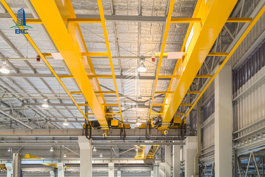
Overhead cranes operate in the upper space above the production line, so they can easily conflict with electrical systems, pipelines, and fire protection equipment. These items need to be coordinated directly in the factory design dossier to avoid relocation, dismantling, or reinforcement after the structure has been completed.
The power supply must simultaneously meet the needs of the hoisting motor, trolley, and crane travel mechanism. Electrical cabinets need protection against overload, short circuit, phase loss, and leakage current. Earthing, lightning protection, and emergency stop buttons must also be arranged in accordance with the equipment and production environment. Power supply routes should be located outside the movement zone of the crane and lifted objects to reduce collision risks.
Air ducts, process pipelines, cable trays, and lighting equipment must not obstruct the runway or lifting height of the crane. The elevations of technical routes must be checked together with rail elevation, roof beams, and operating clearance. Using BIM models or coordination drawings helps detect conflicts between structure, MEP, and equipment early.
Sprinkler heads, fire detectors, smoke extraction systems, and access routes must ensure adequate protection coverage while staying outside the crane collision zone. Areas with dust, high temperature, chemicals, or explosion risks need suitable electrical equipment. Operating procedures must also clearly define danger zones, control signals, equipment inspection requirements, and operator responsibilities.
Design and construction of factories with overhead cranes must be implemented as a unified sequence, where the result of one step becomes the basis for the next. If crane specifications have not been finalized but components have already been fabricated, or if the master layout has not been coordinated with the production line, investors may need to modify the structure, relocate technical systems, and extend the construction timeline.
First, the consultant must survey the site topography, elevations, geotechnical conditions, groundwater level, infrastructure, and transportation conditions. This information determines the foundation solution, floor solution, and erection method. At the same time, the investor needs to provide lifting loads, wheel loads, span, hook height, runway length, operating frequency, goods dimensions, and expansion plans. If input data are not stable, calculation of column spacing, factory height, and runway beams will lack a reliable basis.
The master layout must be organized according to the production line, raw material flow, finished goods flow, forklift movement, and crane operating range. Factory location, warehouses, maintenance areas, roads, transformer stations, and staging areas need to be checked simultaneously. This approach helps reduce operational intersections and prevents the crane runway from being affected by auxiliary buildings or technical infrastructure.
After the design brief is agreed upon, the dossier must fully show the load-bearing frame, columns, column corbels, runway beams, rail elevations, foundations, anchor bolts, and embedded details. Architecture, structure, MEP, and fire prevention and fighting must be coordinated before drawings are issued. Detecting conflicts at this stage is much less costly than demolition, modification, or reinforcement on-site.
Components should only be cut, welded, and painted after fabrication drawings have been checked. Meanwhile, foundations, floors, and anchor bolts must be accepted for elevation, gridlines, and position before frame erection. The erection sequence must ensure temporary stability, followed by inspection of rail straightness, beam elevation, and connection quality to reduce vibration during crane operation.
Testing is not only intended to check whether the equipment operates, but also to evaluate the coordination between the crane, structure, power supply, and protection systems. No-load tests, loaded tests, emergency stops, and travel limits must be checked. After outstanding issues are resolved, the general contractor must hand over as-built drawings, test results, operation manuals, equipment lists, and maintenance plans so the investor can manage the building throughout its service life.
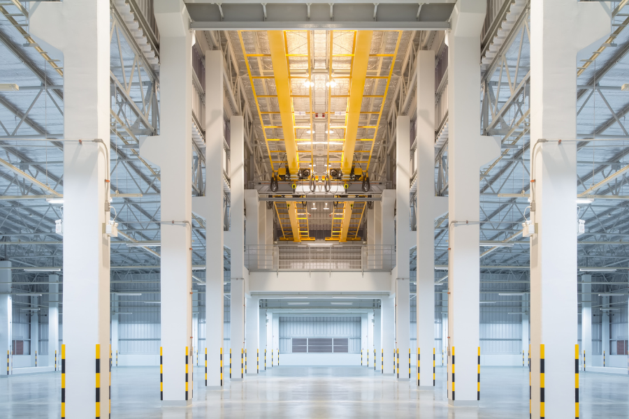
When the overhead crane is not calculated from the beginning, columns, corbels, runway beams, and foundations may not have sufficient load-bearing capacity. Later reinforcement often requires partial dismantling of roofing and wall cladding, affects production activities, and significantly increases costs.
Overhead cranes also generate braking forces, horizontal forces, vibration, and repeated loads during acceleration, deceleration, or stopping. If the design is based only on nominal lifting capacity, the structure may deform, connections may deteriorate quickly, and equipment operation may become unstable.
Differences in span, wheel loads, rail elevation, lifting height, or working mode may cause the equipment to become incompatible with the designed structure. Investors need to finalize specifications with the supplier before completing the dossier and fabricating components.
Without suitable access routes, inspecting rails, hoists, motors, and control cabinets becomes difficult. Crane runways must also avoid conflicts with roofs, lights, fans, cable trays, and fire prevention and fighting systems.
When the business adds machinery or increases output, operating loads may exceed the original capacity. Reserving connection points, structural capacity, and electrical systems from the beginning helps limit reinforcement work and future production interruptions.
Investors should prioritize units that have implemented projects with similar loads, spans, operating frequency, and production industries. Practical experience helps contractors correctly identify wheel loads, braking forces, runway beam requirements, and foundation conditions instead of simply applying a standard steel frame solution.
The design unit must be able to coordinate architecture, structure, MEP, fire prevention and fighting, and infrastructure. If each discipline uses a different set of specifications, the crane may conflict with cable trays, pipelines, or fire protection equipment. Strong coordination capability helps detect issues before dossiers are issued.
Quality must be controlled from materials, cutting, welding, and painting to erection, rail alignment, and connection acceptance. Investors should request inspection dossiers, lifting and erection methods, acceptance standards, and maintenance plans to evaluate actual capability instead of relying only on quotations.
A general construction contractor can help reduce interfaces between the design unit, crane supplier, and construction team. However, the contract must clearly define the scope of equipment, electrical systems, structure, fire prevention and fighting, material standards, handling of additional work, and warranty responsibility. This is the basis for investors to control project cost, schedule, and quality.
Yes, if the columns, foundations, runway beams, and operating clearance meet the new load requirements. Investors need to survey wheel loads, span, lifting elevation, and operating frequency. Some buildings may require structural or roof reinforcement.
Not necessarily. Steel structure is often selected because of its spanning capacity and convenience when arranging runway beams. However, reinforced concrete or combined solutions can still be suitable if they meet load, stiffness, and production condition requirements.
Yes. Specifications should be determined before the construction design dossier is finalized. Lifting load, wheel load, span, hook height, and operating frequency directly affect columns, runway beams, foundations, and factory elevation.
This model is suitable when the project has many interfaces among structure, overhead cranes, MEP systems, fire prevention and fighting, and production lines. One point of responsibility throughout the process helps investors better control schedule, cost, and additional issue handling.
Factory design with overhead cranes must be developed from actual operating data, in which lifting load, wheel load, span, hook height, and working frequency must be determined before structural calculation. These specifications need to be coordinated synchronously with foundations, columns, runway beams, electrical systems, MEP, fire prevention and fighting, and expansion plans.
Investors should choose a unit with synchronized construction design and factory construction capability to reduce conflicts, reinforcement work, and additional costs. BIC can support surveys, design, and construction according to production needs, site conditions, and the specific operating requirements of each project.