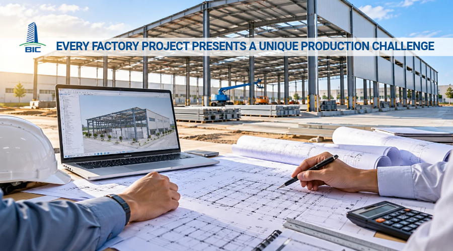
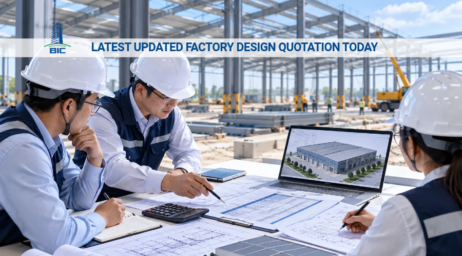
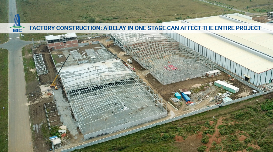
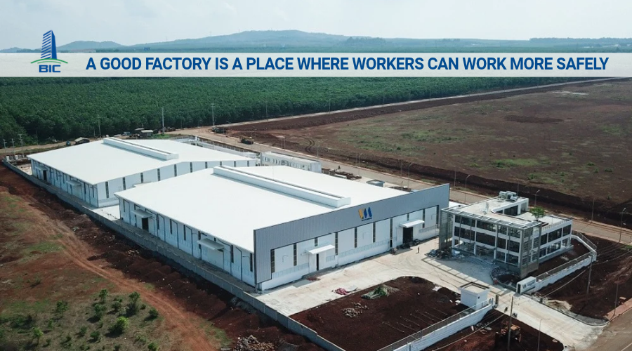
Factory design drawings are the basis for defining the functionality, dimensions, materials, structural solutions, and technical systems of a building. A complete dossier usually includes the master layout, architectural drawings, foundation drawings, structural drawings, MEP drawings, fire prevention and fighting drawings, infrastructure drawings, and details related to the production line.
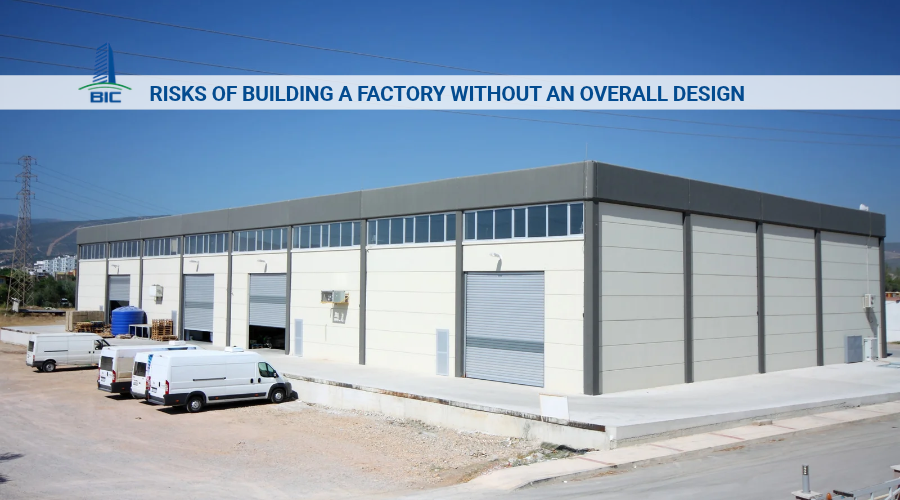
If the drawings lack information or if the disciplines are not properly coordinated, the factory construction process may encounter conflicts between structures, pipelines, and equipment. These discrepancies often lead to demolition, modification, material changes, quantity adjustments, and extended construction schedules.
Therefore, investors need to clearly understand the content of each discipline in order to check functionality, scope, and constructability before approval. In the article below, BIC presents the main components of a factory design dossier, the accompanying documents, and key points to consider when working with a design unit or general construction contractor.
The drawing set is the technical basis throughout the process, from concept development and quantity determination to construction and project handover. Investors need to correctly understand the role of each type of drawing to control scope and avoid using documents incorrectly.
Factory design drawings are a system of documents showing the location, dimensions, materials, construction details, and technical requirements of the building. The dossier converts production line, machinery, and operational needs into solutions that can be calculated, cost-estimated, and constructed. It is also the basis for the investor, design unit, and contractor to agree on the work scope.
A complete dossier usually includes master planning, architecture, structure, foundations, MEP systems, fire prevention and fighting, infrastructure, and environmental treatment. Depending on production characteristics, the dossier may also show machine foundations, overhead cranes, process pipelines, and connection points with equipment.
Concept drawings help investors compare and select solutions. The construction design dossier presents calculations and technical requirements of the building. Construction drawings provide details, dimensions, and specifications for on-site implementation. Contractor shop drawings clarify fabrication and installation methods. Finally, as-built drawings record the actual completed condition to support operation, maintenance, and future renovation.

The accuracy of factory design drawings directly depends on the quality of input data. If the production line, equipment, or site conditions have not been defined, the design unit can only work based on assumptions. This increases the risk of structural adjustments, technical system revisions, and quantity changes during construction.
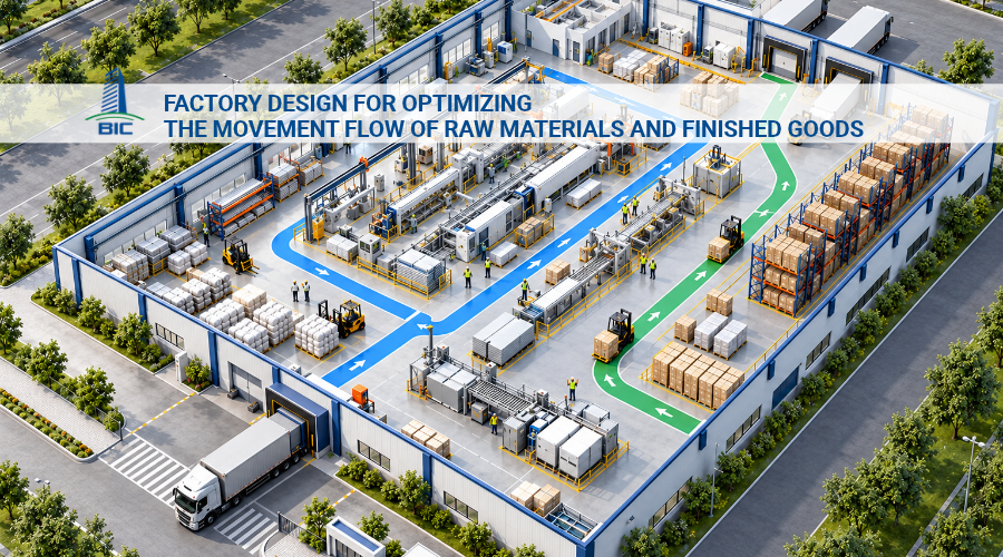
The investor needs to provide the sequence of production stages and the movement direction of raw materials, semi-finished goods, and finished products. Worker flow, forklift flow, and transport vehicle flow must also be defined to organize the layout properly. Requirements related to temperature, humidity, hygiene, dust, and noise will affect zoning, materials, and technical systems.
Equipment information must show dimensions, weight, location, and loads transferred to the floor. Requirements for electricity, water, compressed air, steam, and drainage must be provided for each machine. Sufficient clearance must be reserved around equipment for transportation, installation, operation, and maintenance. This is the basis for defining machine foundations, pipelines, and embedded details.
The site dossier should include boundaries, area, elevation, topography, and geotechnical conditions. The construction design unit also needs information on traffic, electricity, water supply, stormwater drainage, and wastewater connection points. These data determine the master layout, foundation solution, land leveling volume, and infrastructure connection plan.
The investor needs to define production capacity, finishing level, budget, and the expected timeline for putting the factory into operation. If there is a capacity expansion plan, the expansion direction and reserve infrastructure capacity must be clarified. Specific investment objectives help the design unit select suitable solutions, avoiding overdesign or failure to meet future development needs.
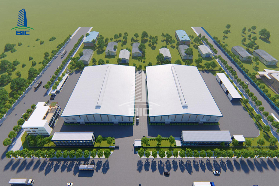
Master layout drawings show how the entire land plot is organized, including the main factory, auxiliary works, traffic routes, and technical infrastructure. This is the basis for evaluating whether the building is suitable for production activities and the company’s long-term development capacity.
The drawings need to show the land boundary, location, dimensions, and distances between buildings. Gridlines, coordinates, and control elevations must be clearly defined to support positioning during factory construction. If the business has an expansion plan, the development direction should also be shown to avoid conflicts with infrastructure that has already been invested in.
Traffic must be arranged according to the characteristics of trucks, forklifts, workers, and fire trucks. Loading and unloading areas must provide sufficient access, stopping space, and turning space. Proper traffic separation helps reduce intersections, limit congestion, and ensure that goods movement does not affect production areas.
Offices, guard houses, parking areas, transformer stations, water tanks, pump stations, and wastewater treatment areas should be placed in locations convenient for operation. These works must connect with the main factory without obstructing traffic or future expansion directions. Waste collection areas should also be arranged according to the collection and treatment process.
Investors need to compare the master layout with the production line, storage needs, and loading/unloading frequency. Finished floor elevations, drainage direction, and infrastructure connection points must be checked before approval. A suitable option must support current operations while allowing future expansion without interrupting operating areas.
Architectural drawings show spatial division, building form, envelope materials, and operational conditions. Investors need to review this discipline based on production lines, machinery dimensions, and goods movement needs, rather than evaluating only the external appearance.
Floor plans show overall dimensions, gridlines, wall positions, partitions, doors, and the division of functional areas. Production zones, warehouses, offices, technical areas, and worker facilities must be arranged according to usage needs. Circulation routes must support personnel, forklifts, and transport equipment.
Elevations show building height, external appearance, roofing materials, wall cladding, and door systems. Louvers, windows, and daylight panels should be arranged according to ventilation, lighting, and heat control requirements. Colors and corporate identity details are also defined in this drawing group.
Sections clarify the relationship between the floor, structure, roof, and vertical usage space. Investors need to check finished floor elevations, clear height, and reserved space for machinery, overhead cranes, or technical systems. If height is not calculated correctly from the beginning, adjustments after structural completion will be very difficult.
Detail drawings show roofing, wall cladding, doors, gutters, downpipes, and insulation materials. Sheet joints, roof penetrations, and junctions between different materials must be clearly treated to reduce water leakage. Heat resistance, corrosion resistance, and surface hygiene requirements must also be defined according to the production environment.
Door dimensions must be sufficient for moving machinery and goods. Floor, wall, and ceiling materials must be suitable for temperature, humidity, and hygiene requirements. Exits, maintenance areas, and operating clearances must be checked before approval. This comparison helps the factory design dossier meet functional requirements and reduce changes during construction.

Structural drawings define the building’s load-bearing capacity, stability, and service life. The dossier must be prepared based on geotechnical conditions, factory scale, machinery loads, goods loads, and operating conditions. Investors need to provide these data accurately before the design is finalized.
Foundation drawings show the layout, dimensions, elevations, reinforcement, and materials of each component. Depending on geotechnical conditions and loads, the building may use isolated footings, strip foundations, raft foundations, or pile foundations. The positions of pile caps, grade beams, column pedestals, and embedded bolts must be clearly shown to control construction.
The floor dossier must define elevations, material layer build-up, concrete thickness, reinforcement, and joint locations. Each area must be classified according to machinery, goods, and forklift loads. Requirements for flatness, abrasion resistance, dust control, or chemical resistance should also be clearly stated according to production conditions.
Machine foundations are designed according to equipment dimensions, loads, and operating characteristics. The drawings must show bolt positions, technical pits, embedded details, and related pipelines. For equipment that generates vibration, vibration transmission control solutions are required to limit impacts on the floor and nearby structures.
Frame drawings show the positions of columns, beams, rafters, purlins, and bracing systems. Dimensions, materials, elevations, and connection details of each component must be fully defined. The column grid must suit the production line, transportation routes, and machinery positions, avoiding obstruction to production activities.
For factories with overhead cranes, the dossier must show corbels, crane runway beams, rail elevations, and operating clearance. The structural system must be calculated for lifting loads, crane movement, and additional effects generated during acceleration or stopping. Therefore, equipment specifications must be provided before the drawings are finalized.
Investors need to confirm that machinery, goods, forklift, and overhead crane loads have been fully updated. Column spacing must be compared with the production line, while floor details must suit each usage area. Machine foundation positions, bolts, and embedded details must also be coordinated with equipment supplier documents before factory construction begins.

MEP drawings show the systems that provide energy, water, ventilation, and technical utilities for production. The dossier must be developed from the machinery list, operating capacity, and requirements of each area. If equipment data is inaccurate, the system may lack capacity or have connection points arranged incorrectly.
Electrical dossiers show power supply diagrams, transformer station positions, generators, main switchboards, and distribution boards. Cable tray routes, conductors, lighting, grounding, and lightning protection must also be defined. Power capacity for machinery should be calculated according to actual operating modes while considering the possibility of adding equipment in the future.
Water supply and drainage drawings need to show supply sources, water tanks, pump systems, pipe routes, and points of use. Domestic water, production water, stormwater, and wastewater must be defined by system. Elevations and pipe slopes must be coordinated with floors, machine foundations, and external infrastructure to ensure drainage performance.
The ventilation system is designed based on generated heat, number of workers, equipment characteristics, and working environment requirements. The dossier should show fan positions, air intake openings, air ducts, and cooling or air-conditioning equipment. The arrangement must reduce stagnant air zones and avoid affecting the production line.
Depending on the industry, the factory may require compressed air, steam, process water, dust extraction, or exhaust gas extraction systems. The drawings must show capacity, pipe routes, elevations, equipment, and points of use. Pipe materials must suit the temperature, pressure, and properties of the medium during operation.
Each piece of equipment needs clearly defined connection points for electricity, water supply, drainage, compressed air, and related utilities. Connection specifications must be checked against the equipment supplier’s documents. Investors also need to define the responsibilities of the equipment supplier and the general construction contractor to avoid missing scope during installation.
Pipe routes and cable trays must be checked against beams, columns, doors, and maintenance spaces. Technical equipment must not obstruct circulation routes or operating areas. Embedded floor pipelines and cast-in details must be confirmed before concrete pouring. Full coordination helps the factory design dossier be implemented without demolition or modification.
Fire prevention and fighting and environmental drawings are prepared according to the function, scale, stored materials, and production line characteristics. These solutions must be defined early because they directly affect the master layout, architecture, structure, and MEP systems of the factory.
The dossier needs to show zoning solutions, evacuation routes, fire alarm systems, firefighting systems, and firefighting water supply. The positions of water tanks, pump stations, pipelines, sprinklers, fire alarm devices, and emergency lighting must be clearly defined. For buildings requiring smoke extraction, the drawings must also show equipment, duct routes, and controlled areas.
Emergency exits, access routes, and safety clearances must suit the production layout. Fire protection pipelines and equipment must not intersect beams, obstruct machinery, or reduce operating space. Power supply, water supply, and control systems also need to be coordinated with the MEP discipline before construction drawings are issued.
Depending on production activities, the environmental dossier may include wastewater collection, dust extraction, exhaust gas treatment, noise control, and waste collection areas. Stormwater, domestic wastewater, and production wastewater need to be clearly separated to select suitable collection, treatment, and connection solutions.
Investors need to accurately provide information on raw materials, production processes, chemicals, and stored goods. These are the data used by the factory design unit to define suitable solutions. If fire prevention and fighting or environmental requirements are added after architecture, structure, or MEP systems have been completed, the project may require major adjustments to layout, equipment, and construction costs.
Infrastructure drawings show how the factory connects with traffic systems, water supply and drainage, and operational support facilities. Although these items are outside the main production area, they directly affect transportation capacity, flood prevention, and stable operation of the entire factory.
The land leveling dossier defines design elevations, slope directions, and cut-and-fill quantities of the land plot. Elevations must be coordinated with the factory floor, yards, roads, and external drainage points. If an unsuitable elevation is selected, the building may experience water accumulation or require additional filling during construction.
Traffic drawings show roads, yards, parking areas, and loading and unloading zones. Width, turning radius, and pavement structure must suit vehicle types and transport frequency. Areas with frequent heavy truck or forklift movement need separate load calculations.
The drainage system must show flow direction, sewer routes, manholes, invert elevations, and connection points. Stormwater must be collected synchronously from the roof, yards, and internal roads. Investors need to check the elevation difference between the building and external systems to evaluate natural drainage capacity or the need for pumps.
Guard houses, parking areas, transformer stations, water tanks, pump stations, offices, and wastewater treatment areas must be fully shown in terms of location, dimensions, and technical connections. These works should be convenient for operation without obstructing traffic or expansion directions. Including all auxiliary items in the factory design dossier also helps investors correctly determine construction scope and budget.
Approving drawings means confirming that the design solution can move into cost estimation, procurement, and construction. Therefore, investors should not only check presentation format, but also compare the dossier with the production line, machinery, investment scope, and actual site conditions.
The layout must suit the production sequence, storage needs, and transport flow. Investors should check the distance between stages, forklift routes, loading and unloading positions, and working space. Maintenance, cleaning, and equipment replacement areas must also have sufficient space.
Machinery dimensions, positions, loads, and operating requirements must be consistent with the factory design drawings. Electricity, water, compressed air, steam, and drainage connection points need to be checked against equipment supplier documents. If machinery information has not been confirmed, related work items should not be issued for official construction.
The dossier needs to include architecture, structure, MEP, fire prevention and fighting, and infrastructure according to the project scope. Investors must check whether interface points have been coordinated. Responsibilities between the design unit, general construction contractor, and machinery supplier should also be clearly defined at each connection point.
Drawings must show sufficient dimensions, elevations, details, materials, and connection details. Embedded or concealed works need to be determined before concrete pouring and finishing. Investors should also request an evaluation of material supply capacity, installation sequence, and suitability with site conditions.
Drawings, the bill of quantities, and technical specifications must be consistent with each other. Material types and quality standards need to be clearly defined so contractors can quote on the same basis. Items with insufficient data, provisional calculations, or exclusions from the contract scope must be listed before the investor approves the construction design dossier.
Factory design drawings are the basis for converting production needs into solutions that can be calculated, cost-estimated, and constructed. A complete dossier must show the master layout, architecture, structure, foundations, MEP systems, fire prevention and fighting, infrastructure, and connection points with machinery.
Before approval, investors need to compare the drawings with the production line, loads, system capacity, and expansion plan. All disciplines must be coordinated consistently to reduce conflicts, quantity discrepancies, and demolition or modification during factory construction. The dossier must also be detailed enough to serve as the basis for material selection, quotation comparison, and project acceptance.
BIC provides factory survey, design, and construction services based on the actual needs of each project. Synchronized implementation under one general construction contractor helps investors better control functionality, scope, cost, and schedule from the design stage to handover.