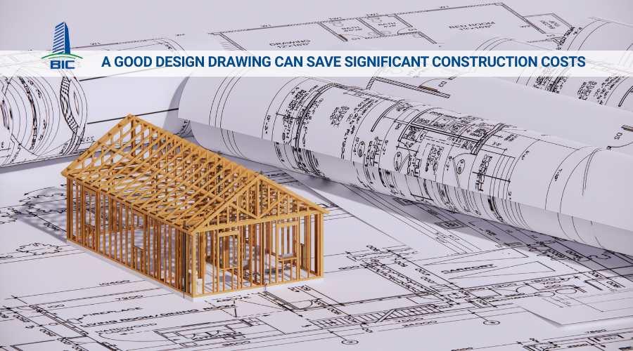
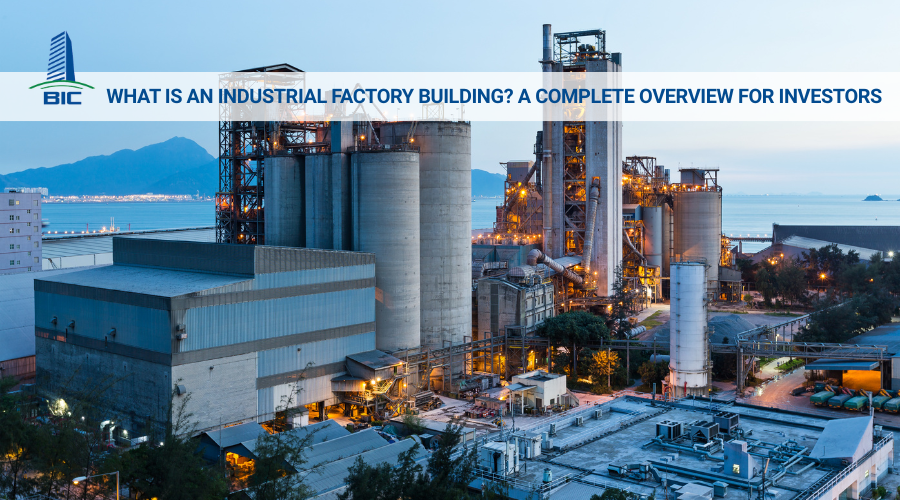
In any factory construction project, the decisive factor that keeps the project on schedule, within budget, and compliant with quality requirements does not start on the job site, it begins with technical design. This stage translates concepts and operational needs into technical requirements that can be constructed, inspected, and operated safely. When technical design is executed properly, conflicts among architecture, structural works, MEP, and fire protection are resolved right on the drawings, minimizing change orders, locking in material costs, optimizing schedules, and improving operational performance throughout the building’s lifecycle.
For investors, technical design is not only a set of detailed drawings; it also forms the foundation for cost estimation, tendering, procurement planning, and quality control matrices. A complete and well-prepared design package enables contractors to present transparent solutions, reduces repetitive requests for information, and facilitates smoother approvals for construction design and fire safety. In this article, BIC clarifies the central role of technical design in factory design and construction, the required documentation scope, coordination procedures, BIM management tools, and key indicators that investors should monitor to ensure sustainable operations from day one.
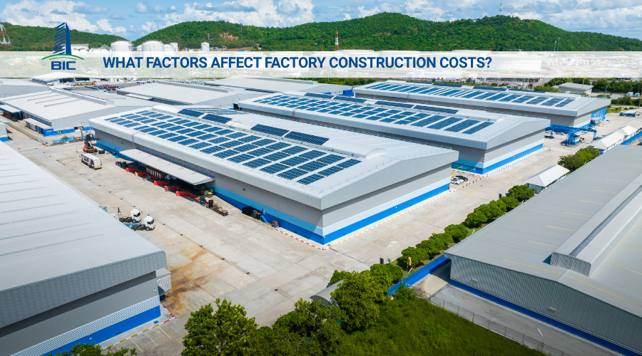
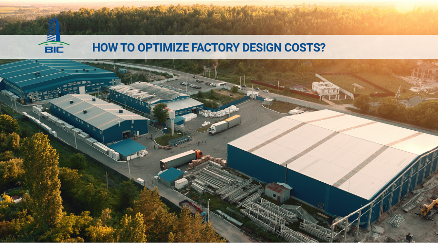
Technical design is the first filter that helps investors control project costs. When the structural model and MEP systems are fully coordinated in the design stage, conflicts such as duct–beam intersections, electrical cabinets overlapping with roller shutter doors, or floor elevation mismatches with manholes are resolved before reaching the job site. With clear technical specifications, contractors can tender using the same baseline, enabling apples-to-apples comparison for the investor.
On this solid foundation, the project team can perform value engineering in a controlled manner to optimize materials and construction methods without compromising durability or function. The result is a cost estimate aligned with actual conditions, lower price volatility, and a wider financial safety margin across the building’s lifecycle.
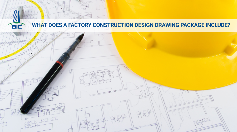
A complete technical design package helps identify key materials early, such as structural steel, roofing sheets, fire pumps, and transformers, giving the supply chain enough time for procurement and preparation. With fewer information gaps, RFI volumes drop significantly, mid-project redesigns are minimized, and the job site no longer needs to pause while waiting for drawings. Site layout planning becomes clearer because tower crane locations, storage yards, and temporary access routes are already incorporated into the construction plan. As a result, progress stays on track, and inspection milestones are not delayed.
Factory quality is not defined by the finishing layer but starts from design parameters. For industrial floors, accuracy in flatness, expansion joints, and load capacity reduces cracking and deflection during use. Well-planned natural lighting and ventilation solutions help reduce heat and dust, creating a better working environment and saving energy. Electrical capacity must be designed to accommodate growth curves, with reserved space and panel capacity for future expansion. These decisions streamline construction and enhance long-term operational efficiency.
Technical design establishes the foundation of safety. Safe working clearances around machinery, technical corridors, evacuation widths, and the number of exits are all calculated upfront to separate pedestrian and vehicle pathways. Closed-loop fire protection networks, sprinkler selection, pump hydraulic calculations, and tank capacity are determined using current standards to ensure required pressure and flow for all scenarios.
Safety requirements such as fall protection, collapse prevention, and lockout–tagout protocols should be embedded in the design from the beginning, helping contractors develop safe construction plans, reduce preparation time, and minimize risks on-site. In other words, a robust technical design package serves as both a construction roadmap and a protective barrier for people, assets, and project timelines.
Decisions made in the foundation stage directly affect durability and operational capability. Technical design must be based on geotechnical surveys with adequate depth and borehole density to determine bearing capacity, groundwater levels, and soil settlement characteristics. From this data, the engineer selects shallow foundations or piles, determines floor elevation, bedding layers, and reinforcement for machinery loads and internal traffic.
For industrial floors, the design must address load-bearing capacity, flatness, expansion joint control, and long-term crack prevention. Specifications should include concrete grades, subbase structure, reinforcement, surface hardening solutions, and large-panel floor systems when appropriate. At column bases and crane areas, calculations must control differential settlement, with machine plinths and anchoring details to reduce vibration and maintain precision.
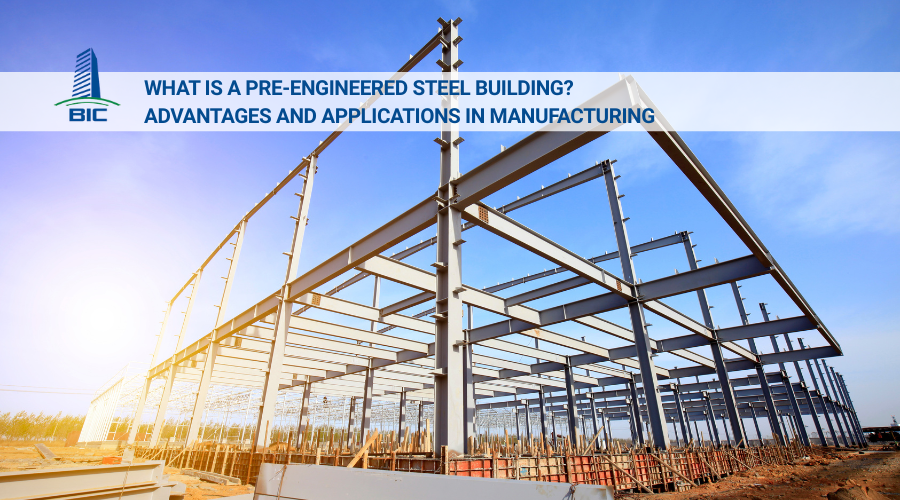
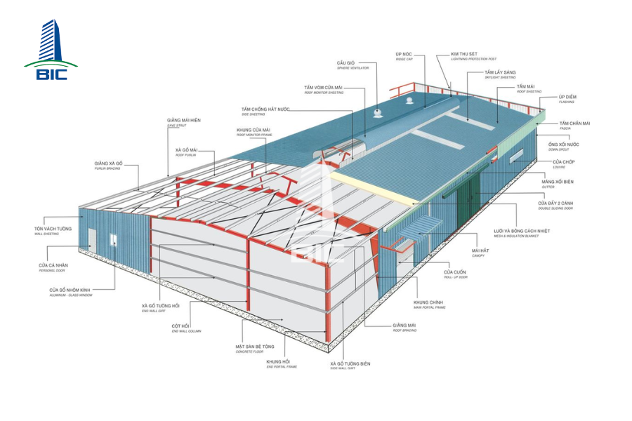
The structural system must demonstrate safety under unfavorable load combinations—including dead load, live load, wind, crane load, and suspended equipment. Load paths, beam–truss spans, permissible deflection, and lateral displacement must be clearly calculated to ensure overall rigidity. Construction design drawings should detail plate connections, anchor bolts, stiffeners, erection sequence, and temporary stability requirements.
Industrial environments require stringent corrosion protection. The design must specify paint or galvanization systems, coating thickness, surface preparation standards, adhesion tests, and acceptance criteria. For concrete structures, mix design, curing, construction joints, and waterproofing details for special areas must be clearly defined.
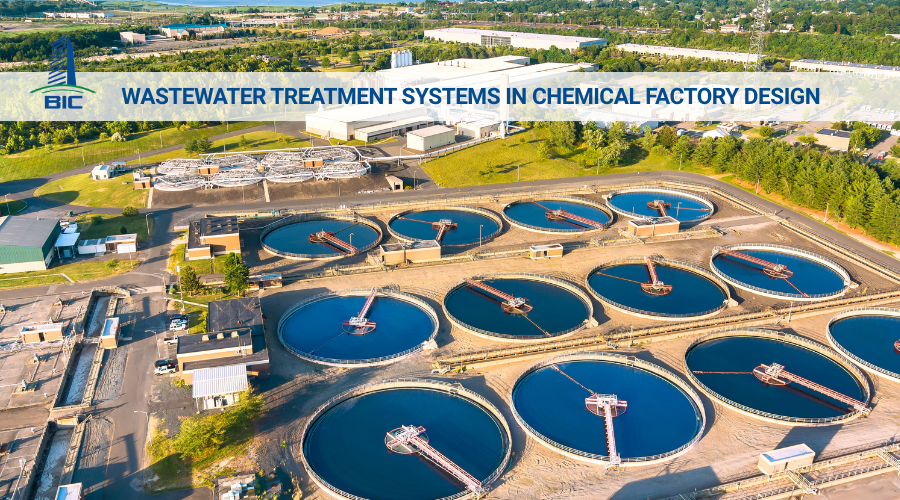
MEP systems are the lifeline of an industrial facility. Drawings must define transformer capacity, generator backup configuration, ATS diagrams, lightning protection, grounding networks, and future capacity expansion plans. Water supply must include hourly flow demand, minimum pressures, water quality for production, tank layouts, pump stations, and looped piping for stability.
For industries requiring compressed or process air, technical design must include utility corridors, compressor room layout, main piping routes, condensate drainage, and allowable leakage rates. Ventilation and HVAC must be calculated based on heat and moisture loads, with supplementary solutions such as cooling pads or rooftop units when needed, ensuring separation between clean and polluted airflow to prevent contamination.
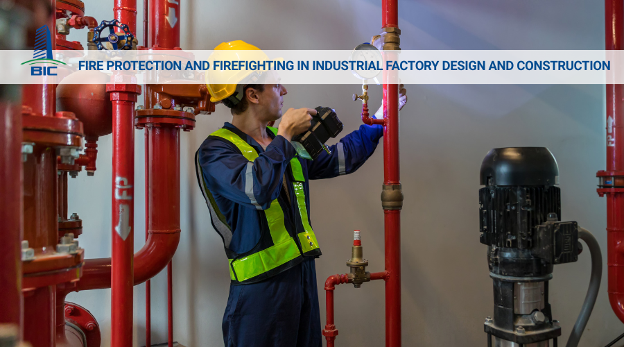
Fire protection must be integrated from the start and strictly follow applicable regulations. The design should include hydraulic calculations to determine pump flow, working pressure, tank volume, and loop ring configurations combined with sprinklers or specialized systems. Fire compartments, fire barrier solutions, evacuation routes, emergency lighting, and signage must be shown clearly on plans and sections.
The design package must also include pump room layout, fire alarm control center, fire hose cabinet locations, hydrants, and exterior fire truck access. Equipment schedules, testing standards, and power-loss response scenarios should accompany the package to support regulatory approvals and proper installation by contractors.
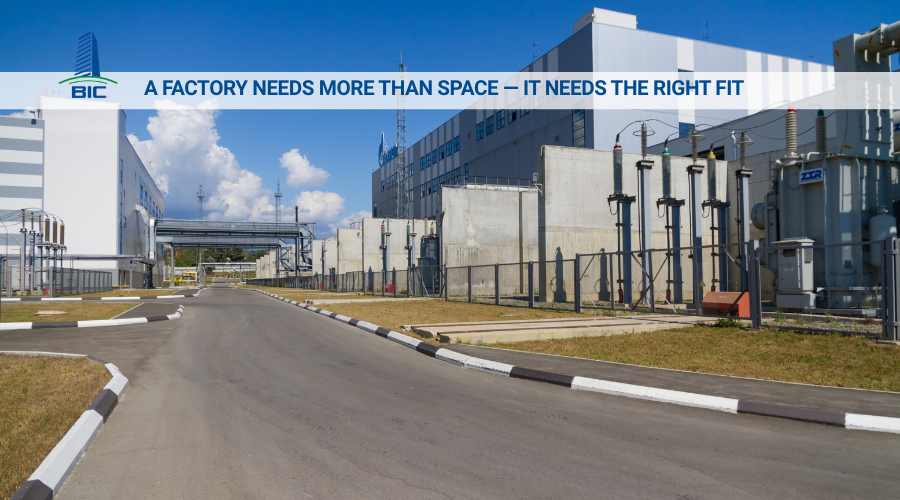
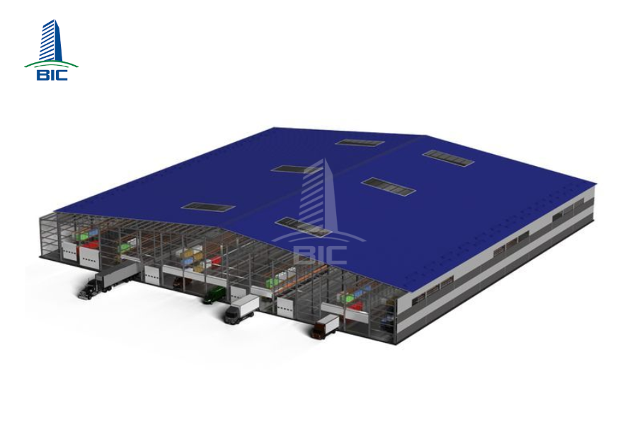
Internal logistics capacity determines daily throughput. Technical design should define main and auxiliary gates, separated inbound/outbound lanes, container yards, truck turning radius, and allowable load of internal roadways. Site elevation must ensure proper drainage, with channels, manholes, and discharge points calculated for design rainfall.
Support facilities security booths, checkpoints, truck scales, camera systems, and loading area lighting—must be clearly defined with capacity, illumination levels, and coverage zones. Clear representation of these items on the drawings ensures smooth construction, fewer field adjustments, and shorter commissioning time before operations begin.
The process begins at the feasibility stage by defining investor requirements and applicable standards. This is when target capacity, planning indicators, material standards, environmental requirements, and safety criteria are finalized. Based on this foundation, the consultant develops technical design and detailed cost estimates with sufficient depth for tendering and long-lead procurement.
The package is then submitted for construction design and fire protection approvals, including narrative reports, calculations, drawings, and evacuation simulations. After approvals, the investor issues tender documents, conducts capability, technical, and financial evaluations, selects contractors, and prepares mobilization plans and groundbreaking milestones.
Once contractors join the project, technical coordination must operate in a unified rhythm. All clarification requests are managed through an RFI system with clear deadlines and responsible parties. Contractor shop drawings must adhere to the approved technical design and be reviewed by the consultant before fabrication or installation. Regular coordination meetings among architecture, structure, MEP, and fire protection help identify conflicts early and finalize solutions directly on the model or drawings.
Any design change must follow a controlled change management process: scope description, impact analysis, approval records, and updates to reissued documents to ensure everyone builds according to the same version. Upon installation completion, as-built drawings must reflect actual field measurements, serving as the foundation for inspection, maintenance, and operation.
Inspection must function as a sequence of clear checkpoints. Before concrete pouring, steel column erection, or MEP installation, consultants and supervisors inspect dimensions, elevations, anchorage, safety measures, and site readiness. At the technical commissioning stage, each system is tested individually, then tested in-integrated mode to evaluate overall operational performance.
Fire protection undergoes pressure tests, flow tests, alarm testing, and evacuation drills before submission for approval by authorities. Once all criteria are met, the project proceeds to final acceptance, issue punch lists, implement corrective actions, submit as-built documentation, deliver O&M manuals, spare part lists, and conduct operator training. The handover and warranty bond mark the transition from construction to stable operation.

In technical design for industrial factories, BIM acts as a single digital model linking architecture, structure, MEP, and fire protection. When every system is modeled in 3D, conflicts between beams and ducts, cable trays and cranes, or electrical panels and exits are identified and resolved early before construction. This significantly reduces RFIs and change orders, shortens time for shop drawing preparation and material procurement, as data is aligned from the start. After handover, the model continues as a digital twin for maintenance, asset management, equipment replacement planning, and future expansion without re-surveying the facility.
For BIM to deliver real value, model development levels must be clearly defined for each discipline. Structure must reach LOD sufficient for span checks, member sizes, connections, and plate details for procurement. MEP must include actual component sizes, elevations, bend radii, and maintenance clearances to validate installation feasibility. Fire protection must accurately model sprinkler locations, hydrants, ring pipes, and pump rooms for hydraulic calculations and approvals. Architecture must show setbacks, floor elevations, evacuation paths, and technical spaces. Infrastructure must display gates, yards, roads, and drainage elevations for logistics checks. All components must follow standardized naming and attribute systems to support cost estimation, quantity takeoff, material management, and asset management.
Effective BIM management relies on a disciplined coordination cycle. Each model release must include a clash list with priorities and deadlines for resolution. From the consolidated model, the cost team extracts material and system quantities and reconciles them with procurement schedules to lock in budgets. As construction completes each component, the model is updated with actual installation data and becomes a digital as-built record aligned with inspection documents, maintenance specs, and spare parts lists. Through this workflow, BIM evolves from a design tool into an end-to-end platform for construction, commissioning, and factory operations.

The most common risks from inadequate technical design stem from dimensional and elevation inconsistencies between disciplines, leading to conflicts during installation. Ducts hitting beams, cable trays interfering with crane paths, MEP ladders blocking evacuation routes, or floor elevation mismatches with drainage elements all force construction stoppages for cutting and rework—resulting in cost overruns and schedule delays. Minor drawing errors often escalate into major site problems if undetected early.
Another risk group arises from inappropriate load design. Industrial floors with insufficient flatness or load capacity will crack or deflect under forklifts or storage systems. Crane beams or column bases incorrectly designed for service loads will cause excessive vibration, posing operational hazards. These issues are difficult to fix once the facility is operational.
Fire protection risks are also critical. Undersized fire pumps, incorrect sprinkler density, inadequate tank volume, poor fire truck access, or excessive evacuation distances can all lead to rejection during authority inspections and increased operational hazards. If fire protection is noncompliant, the factory cannot start operations even if all other components are complete.
The most effective prevention strategy is establishing cross-check and independent review mechanisms before issuing design documents. Each design stage should undergo internal quality control followed by independent clash detection across architecture, structure, MEP, and fire protection using 3D models. Conflict detection and resolution must follow standardized procedures with clear responsibility and timelines to ensure all changes are consistently incorporated.
Simultaneously, internal logistics simulations should be performed to validate movement flows for people and vehicles. Calculations for truck turning radius, container yard capacity, pedestrian–vehicle segregation, controlled intersections, and signage help prevent future congestion and accidents. Simulation results must translate into design details such as lane width, ramp elevations, gate geometry, and lighting plans.
During construction and commissioning, on-site tests are the final protective layer. Floors must be checked for flatness and load tested under real operating conditions. Crane structures must be aligned, deflection measured, and certified according to standards immediately after installation. Fire protection systems require pressure tests, flow measurements at the farthest hydrant, pump testing in multiple modes, and integrated drills with the fire alarm system. Only after all metrics meet standards should the project proceed to final acceptance.
When independent review, logistics simulation, and on-site testing are applied rigorously, risks from weak technical design are eliminated earlyensuring the project achieves timely, safe, and sustainable operations throughout its lifecycle.
Technical design is the backbone of a successful factory construction project. If you want to shorten implementation time and maintain strong budget control, start with a thorough technical design review. BIC is ready to support you from feasibility to operational handover, including standardization of applicable codes, BIM planning, fire protection approvals, cost estimation, and supply chain scheduling. A well-prepared technical design package today will become a long-lasting competitive advantage for your factory tomorrow.